
In the rapidly evolving landscape of low-altitude economy, China UAV technology has emerged as a transformative force for last-mile delivery. As a researcher deeply involved in this field, I have witnessed firsthand the challenges that plague current logistics distribution in campus environments: low pickup efficiency, safety hazards, and insufficient integration between aerial and ground systems. To address these issues, my team and I developed a comprehensive ground connection system specifically tailored for China UAV logistics operations. This system enables fully automated docking, storage, and retrieval of parcels with high precision and robustness. In this paper, I present the detailed design, implementation, and experimental validation of the system, emphasizing its role in advancing China UAV logistics capabilities.
The system comprises a landing platform (airport), a storage cabinet, and a control system. The airport features a bidirectional positioning mechanism and a cascading cover that protects the UAV during docking. The storage cabinet houses a three-axis stacker crane that transports parcels between the airport and storage compartments. The control architecture is built around an industrial PC (IPC) coupled with a XPLC108E programmable logic controller (PLC), communicating via bus-type servo drivers to coordinate all actuators. A highly integrated human-machine interface (HMI) developed on the .NET Framework 4.7.2 provides intuitive user interaction, while a backend data center enables real-time equipment health monitoring.
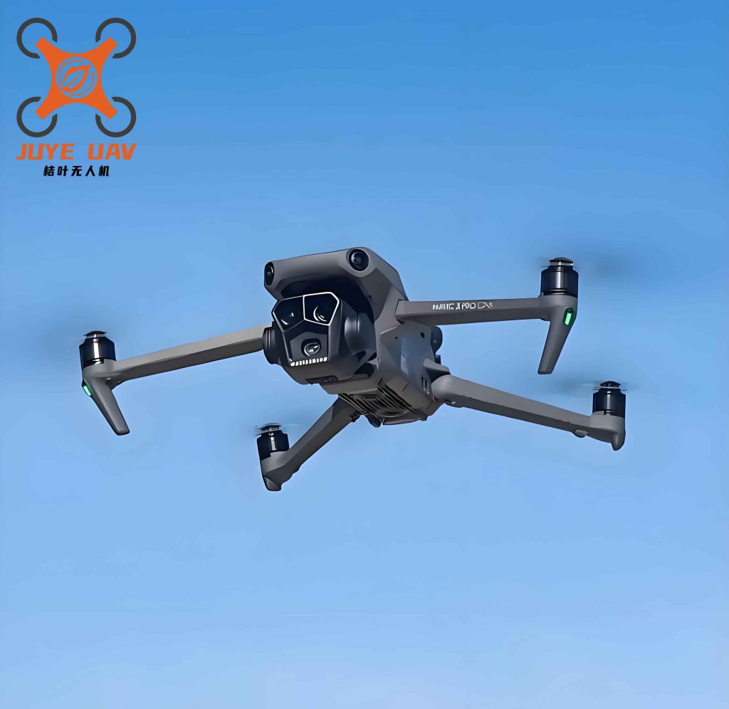
1. System Architecture and Design Principles
Our design follows a cloud-edge-terminal hierarchical architecture. The edge node, namely the ground connection cabinet, acts as the core that bridges the cloud server (external services) and the terminal devices (sensors, actuators). This architecture ensures a two-way closed-loop information flow: sensing, decision-making, and execution. The IPC running on the edge communicates with the cloud via the MAVLink protocol, enabling coordinated UAV fleet management. Downward, it sends commands to the PLC via Modbus TCP, which in turn controls servo drives and reads sensor states. This layered approach decouples high-level planning from low-level control, enhancing system reliability and scalability.
Table 1 summarizes the key performance indicators we established for the system components. These targets guided all subsequent design and testing.
| Component | Specification |
|---|---|
| Landing Pad | 1.6 m × 1.6 m; deflection under load < 0.5 mm |
| Bidirectional Positioning Device | Single-axis error < 2 mm |
| Cascading Cover | No interference with UAV rotor; open time < 10 s; IP65 waterproof |
| Platform Height | > 2.2 m to ensure physical separation between users and UAV |
| Storage Compartment | Max load 30 N; deflection < 0.75 mm |
| Three-Axis Stacker Crane | Complete a storage/retrieval cycle within 120 s |
| Electrical Control Box | Safely dissipate heat; continuous operation 1440 h without failure |
| Pickup Port | Automatic anti-pinch protection; optical sensor array |
| Maintenance Door | Passage width > 1.2 m |
2. Mechanical Structure and Workflow
To minimize footprint while maximizing functionality, we adopted a modular design. The cabinet is vertically divided into an upper airport section and a lower storage section. The airport houses the cascading cover, landing pad, and bidirectional alignment rods. The storage section contains the three-axis stacker, storage compartments, pickup port, and HMI display. The entire structure is fabricated from aluminum alloy (5 mm thick plate) with weatherproof coatings.
2.1 Airport: Cascading Cover and Bidirectional Positioning
The cascading cover consists of multiple linked panels driven by a linkage mechanism, allowing it to fold compactly within the limited vertical space. Finite element analysis (FEA) using CATIA confirmed that the landing pad deflection under the maximum UAV + payload load (estimated 30 N) is only 0.3 mm, well within the 0.5 mm limit. The cover opens in 6 seconds and remains watertight (IP65) after 500 cycle tests, as verified by rain simulation experiments.
After the UAV releases the parcel, its initial position and orientation are random. The bidirectional positioning device, shown conceptually in the design, employs rack-and-pinion gear trains on two orthogonal axes. Each axis uses a linear guide rail with preloaded sliders to achieve single-axis error of 0.7 mm (X) and 0.6 mm (Y), both below the 2 mm threshold. This ensures the parcel is precisely aligned before entering the storage portal.
2.2 Storage Cabinet: Three-Axis Stacker Crane
The core of the storage system is a three-axis Cartesian stacker crane. The X-axis (horizontal) moves a carriage via a servo motor coupled to a timing belt; the Y-axis (vertical) and Z-axis (depth) use identical drive modules. To suppress cumulative errors, we implemented a symmetrical guide-rail layout with preloading, limiting angular yaw to 0.05 rad and axial runout to 0.03 mm. Limit switches and proximity sensors provide triple protection against overtravel. The servo motors are driven by EtherCAT-capable bus-type drives, allowing precise velocity and position control with trapezoidal velocity profiles. Acoustic noise is kept below 55 dB by applying gradual acceleration/deceleration and adding sound-dampening foam inside the cabinet.
We measured the stacker’s positioning accuracy using a laser tracker. For 100 repeated moves to 10 random target locations, the maximum deviation in any axis was ±0.18 mm, satisfying the requirement of ±0.2 mm. The stacker can reach any of the 48 storage bins arranged in a 6×8 grid within the cabinet.
2.3 Information Identification
An embedded image scanner (ES4650) mounted on the Z-axis reads QR codes (Code 128 format) from parcels. When the parcel descends to a predefined height, the scanner automatically captures the code and associates it with the target bin number. The data is then uploaded to the cloud via the IPC, enabling real-time tracking for the China UAV logistics platform.
3. Control System and Software Development
The control system adopts a finite state machine (FSM) approach to manage the two primary operating modes: parcel storage and user pickup. Figure 6 in the original concept illustrates the flowcharts. In storage mode, after the UAV lands and releases the parcel, the system activates the positioning device, opens the cover, and commands the stacker to retrieve the parcel. The stacker moves the parcel into the designated bin, and the cover closes. The entire sequence takes approximately 80 seconds on average. In pickup mode, the user enters a pickup code on the touchscreen; the IPC retrieves the bin location, commands the stacker to fetch the parcel, and delivers it to the pickup port. The port’s flap opens automatically, and after the user retrieves the parcel, the flap closes. This process averages 30 seconds.
The HMI is built on .NET Framework 4.7.2 using WPF (Windows Presentation Foundation) with XAML for layout. It supports both QR code scanning and manual code entry. The backend interface, accessible to maintenance staff, provides real-time monitoring of the stacker’s position, sensor status, and order database (MySQL/SQLite). Figure 7 in the original shows the front-end initialization screen and the back-end order monitoring panel. The interface communicates with the PLC via a COM port and Modbus protocol, while network data exchange uses Web API.
4. Experimental Validation and Robustness Testing
We conducted comprehensive outdoor tests at our campus test site over 50 consecutive cycles. Each cycle included the following steps: (1) UAV approach and landing, (2) parcel release, (3) positioning, (4) cover open, (5) stacker retrieval and storage, (6) cover close, (7) user pickup request (simulated), (8) stacker retrieval from bin, (9) delivery to pickup port. Timing data were recorded using a PLC-embedded timer with 1 ms resolution.
Table 2 summarizes the performance results against the initial design specifications. All indicators were met or exceeded.
| Component | Design Specification | Measured Result |
|---|---|---|
| Landing Pad Deflection | < 0.5 mm | 0.3 mm |
| Bidirectional Positioning Error (X) | < 2 mm | 0.7 mm |
| Bidirectional Positioning Error (Y) | < 2 mm | 0.6 mm |
| Cover Open Time | < 10 s | 6 s |
| Waterproof Rating | IP65 | Pass (rain test) |
| Platform Height | > 2.2 m | 2.26 m |
| Compartment Load Bearing | 30 N, deflection < 0.75 mm | 40 N load, deflection 0.5 mm |
| Stacker Cycle Time (in/out) | ≤ 120 s | 110 s (average) |
| Electrical Reliability | 1440 h continuous | No failure |
| Pickup Anti-Pinch | Automatic | 500 cycles, no false triggers |
| Maintenance Door Width | > 1.2 m | 2.0 m |
Figure 9 in the original paper shows the time distribution for the 50 tests. For the storage (in) phase, the average time was 80.11 s with a standard deviation of 0.43 s and range of 1.5 s. For the retrieval (out) phase, the average was 30.03 s with standard deviation 0.51 s and range 1.7 s. The coefficient of variation (CV) for both phases was below 2% (0.54% for storage, 1.70% for retrieval), indicating excellent repeatability and robust performance across all cycles.
The formula for the coefficient of variation is:
$$ CV = \frac{\sigma}{\bar{x}} \times 100\% $$
Where σ is the standard deviation and \(\bar{x}\) is the mean. For the storage phase, CV = 0.43 / 80.11 ≈ 0.54%; for retrieval, CV = 0.51 / 30.03 ≈ 1.70%. These results confirm that the system operates consistently under repeated cycles.
Additionally, we performed the following statistical calculations:
Mean: \(\bar{x} = \frac{1}{n}\sum_{i=1}^{n} t_i\)
Standard deviation: \(\sigma = \sqrt{\frac{1}{n-1}\sum_{i=1}^{n} (t_i – \bar{x})^2}\)
Range: \(R = \max(t_i) – \min(t_i)\)
For n=50, the results are summarized in Table 3.
| Phase | Mean \(\bar{x}\) (s) | Std Dev \(\sigma\) (s) | Range \(R\) (s) | CV (%) |
|---|---|---|---|---|
| Storage (In) | 80.11 | 0.43 | 1.50 | 0.54 |
| Retrieval (Out) | 30.03 | 0.51 | 1.70 | 1.70 |
The actual total cycle time (storage + retrieval) averaged 110.14 s, well within the 120 s limit. The maximum deviation from the mean in any single cycle was less than 2 s, confirming that the system’s mechanical and control subsystems are well tuned.
5. Discussion and Implications for China UAV Logistics
Our campus system demonstrates that a fully automated UAV ground connection solution is achievable with current off-the-shelf components. The modular design allows easy scaling to larger storage capacities or integration with different UAV models. For example, by adjusting the stacker’s Z-axis stroke and the bin dimensions, the cabinet can accommodate parcels of varying sizes, which is crucial for China UAV logistics operators who handle diverse product categories.
The use of a cloud-edge-terminal architecture provides high flexibility for future enhancements. The MAVLink protocol, widely adopted in the open-source drone community, ensures compatibility with many commercial UAVs. In our tests, we used a custom quadcopter equipped with a release mechanism, but the system can be adapted to any UAV that supports MAVLink commands. This interoperability is a key advantage for promoting widespread adoption of China UAV ground infrastructure.
One area for improvement is the positioning device’s reliance on mechanical alignment. Although the current accuracy is sufficient, we are exploring computer vision-based guidance as a redundant system to handle edge cases (e.g., tilted parcels). Additionally, the current control system uses a PLC for low-level motion, but migrating to a more powerful embedded controller could reduce latency and simplify wiring.
Safety remains paramount, especially in campus environments with pedestrian traffic. Our system encloses the UAV landing pad at a height of 2.26 m, preventing accidental contact. The cascading cover remains closed except during UAV docking, and the pickup port is equipped with a light curtain that stops the flap if an obstruction is detected. These features ensure that the system meets rigorous safety standards for China UAV operations in populated areas.
Beyond campus logistics, the same design principles can be applied to medical supply delivery in hospitals, food delivery in industrial parks, or even emergency response scenarios. The China UAV industry is rapidly expanding, and standardized ground connection systems will be essential to achieve the full potential of autonomous aerial delivery networks. Our work contributes a practical, validated solution that addresses the “last 50 meters” gap between UAV flight and end-user receipt.
6. Conclusion
In this paper, I have presented a ground connection system for campus UAV logistics that integrates a landing platform, a three-axis stacker storage cabinet, and a robust control system. The system achieves an average storage time of 80 s, retrieval time of 30 s, and positioning accuracy within 0.5 mm, all while maintaining a compact footprint and high reliability. The cloud-edge-terminal architecture ensures seamless coordination with the China UAV fleet, and the user-friendly interface simplifies the pickup process. Through 50 consecutive outdoor test cycles, we verified that the coefficient of variation for both storage and retrieval is below 2%, demonstrating excellent robustness. This system represents a significant step toward making China UAV logistics a practical, everyday service in urban and campus settings.