
The maintenance of extensive road networks presents a significant logistical challenge, often straining conventional manual inspection methods. Limited human resources struggle to achieve comprehensive and timely identification of pavement distresses such as cracks, potholes, and surface deformations, leading to potential safety hazards and accelerated infrastructure deterioration. In response to this challenge, we propose and have developed an integrated quadrotor drone system specifically designed for automated road quality assessment. Leveraging the inherent advantages of quadrotor drones—including exceptional maneuverability, stable hovering capability, and operational flexibility—this system enables efficient, non-contact inspection across diverse and potentially hazardous terrains, thereby enhancing detection efficiency and reducing labor dependency.
The core philosophy of our design is to integrate a robust autonomous flight platform with a suite of specialized sensors and real-time data processing modules. The system is architected to perform pre-defined inspection missions, collecting multi-modal data which is processed both onboard and at a ground station to provide actionable insights into road surface conditions. This approach transcends the limitations of ground-based vehicles, offering a unique aerial perspective that is unobstructed by traffic and capable of covering large, continuous stretches of roadway rapidly.
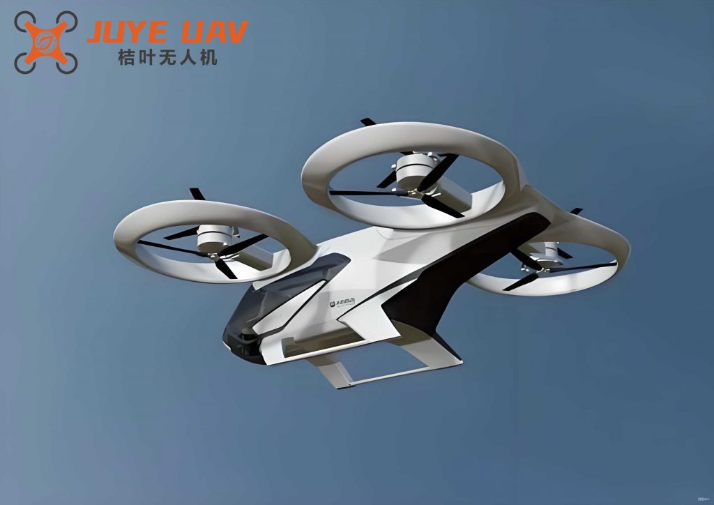
The fundamental configuration of our quadrotor drone is the symmetric “X” or “+” layout, where four rotors are placed at the ends of a cruciform frame. This configuration provides balanced thrust and torque control. The dynamic model of a quadrotor drone is a highly coupled, under-actuated system. Its motion is governed by adjusting the rotational speeds of the four motors ($\omega_1, \omega_2, \omega_3, \omega_4$). The total thrust $T$ and the torques around the body axes ($\tau_\phi, \tau_\theta, \tau_\psi$) are related to the motor speeds by:
$$
\begin{bmatrix} T \\ \tau_\phi \\ \tau_\theta \\ \tau_\psi \end{bmatrix} =
\begin{bmatrix}
k_F & k_F & k_F & k_F \\
0 & -k_F L & 0 & k_F L \\
k_F L & 0 & -k_F L & 0 \\
k_M & -k_M & k_M & -k_M
\end{bmatrix}
\begin{bmatrix} \omega_1^2 \\ \omega_2^2 \\ \omega_3^2 \\ \omega_4^2 \end{bmatrix}
$$
where $k_F$ is the thrust coefficient, $k_M$ is the drag torque coefficient, and $L$ is the arm length from the center of mass to a motor. This equation forms the basis for the flight controller to translate desired attitude and altitude commands into precise motor inputs.
System Architecture and Design
The overall system architecture is divided into three primary functional layers: the Flight Control and Navigation Layer, the Sensor Data Acquisition and Processing Layer, and the Ground Control and Communication Layer. A high-level block diagram of the integrated system is presented below, illustrating the interconnection and data flow between these core components.
| Module Category | Component | Key Specification / Model | Primary Function |
|---|---|---|---|
| Flight Control | Main Processor | STM32H743 (Cortex-M7) | Runs PX4 autopilot stack, handles navigation & stabilization. |
| Inertial Measurement Unit (IMU) | ICM-42688-P | Provides high-fidelity accelerometer and gyroscope data. | |
| GPS Module | Integrated with flight controller | Provides global positioning for waypoint navigation. | |
| Sensor Payload | Peripheral Controller | STM32F103 (Cortex-M3) | Manages sensor data collection, filtering, and forwarding. |
| Machine Vision Unit | Kendryte K210 with OV2640 Camera | On-board road crack detection using a deep learning model. | |
| Visual Streaming Module | ESP32-CAM | Provides real-time video feed to the ground station. | |
| Infrared Thermometer | MLX90614 | Non-contact surface temperature measurement. | |
| Environmental Sensor | DHT11 | Measures ambient temperature and humidity. | |
| Gas/Smoke Sensor | MQ-5 | Detects concentrations of combustible gases (e.g., from vehicles). | |
| Distance Sensor | Infrared Proximity Module | Measures distance to ground/obstacles for altitude hold or mapping. | |
| Communication | Telemetry Radio | 3DR/SiK compatible | Bidirectional data link between quadrotor drone and Ground Control Station (GCS). |
| Ground Station | Software | QGroundControl (QGC) | Mission planning, real-time monitoring, and data visualization. |
Hardware Implementation
The airframe is based on a standard F450-size quadrotor drone kit, offering a favorable balance between payload capacity, stability, and agility. The selection of electronic components was driven by requirements for computational power, reliability, and low weight.
The flight controller is the central nervous system of the quadrotor drone. We employed a commercial flight controller (Nora+) built around the powerful STM32H743 microcontroller. This processor, with its dual-precision floating-point unit, is essential for running the complex mathematical algorithms of the PX4 autopilot stack with high efficiency. The integrated ICM-42688-P IMU offers superior noise performance and reduced temperature drift, which is critical for maintaining stable flight and accurate position estimation, especially during long-duration inspection missions.
A custom-designed sensor integration board, centered on an STM32F103 microcontroller, serves as the data acquisition hub for all peripheral sensors. This decentralized architecture offloads the sensor polling and basic signal conditioning from the main flight controller, ensuring that flight control loops are not interrupted. This board gathers analog and digital data from the various environmental and ranging sensors, packages it, and transmits it to the ground station via the telemetry link.
Machine Vision for Crack Detection
A pivotal component of our road inspection quadrotor drone is the machine vision system. We utilize the Kendryte K210 system-on-chip (SoC), which features a dedicated convolutional neural network (KPU) hardware accelerator. This allows for real-time image analysis onboard the quadrotor drone without relying on ground station computing power, a crucial feature for autonomous decision-making or alerting.
The K210 is paired with an OV2640 camera module. We developed a crack detection model based on a streamlined version of the YOLOv3 (You Only Look Once) architecture. The model was trained on a large dataset of road surface images containing various types of cracks and distresses. The training process involves optimizing the network parameters ($\mathbf{W}$ weights and $\mathbf{b}$ biases) to minimize a loss function $\mathcal{L}$ that measures the discrepancy between predicted bounding boxes/classes and the ground truth annotations from the training data.
$$
\mathcal{L}(\mathbf{W}, \mathbf{b}) = \lambda_{\text{coord}} \sum_{i=1}^{S^2} \sum_{j=1}^{B} \mathbb{1}_{ij}^{\text{obj}} \left[ (x_i – \hat{x}_i)^2 + (y_i – \hat{y}_i)^2 \right] + \cdots
$$
Where $S^2$ is the grid size, $B$ is the number of bounding box predictors, $\mathbb{1}_{ij}^{\text{obj}}$ indicates if the $j$th predictor in cell $i$ is responsible for an object, and $(x_i, y_i)$ are the predicted box center coordinates. The trained model is converted into a `.kmodel` file, which is loaded onto the K210. During flight, each captured frame is processed through this network. If a crack is detected with a confidence score exceeding a predefined threshold (e.g., 85%), the event is logged with a timestamp and GPS coordinates, and an alert can be sent to the ground operator.
Specialized Sensor Suite
The inspection capability of the quadrotor drone is augmented by a suite of sensors providing complementary data streams:
- Infrared Temperature Sensor (MLX90614): Operates on the principle of detecting infrared radiation emitted by the surface. The sensor’s output voltage $V_{\text{out}}$ is proportional to the target’s radiated power. The object temperature $T_{\text{obj}}$ is derived internally using the Stefan-Boltzmann law and emissivity settings. For high accuracy, a calibration function $f_{\text{cal}}(V_{\text{out}}, T_{\text{amb}})$ can be applied, often determined empirically. $$ T_{\text{obj}} \approx f_{\text{cal}}(V_{\text{out}}, T_{\text{amb}}) $$
- Environmental Sensors (DHT11, MQ-5): The DHT11 provides digital readings of ambient temperature and humidity. The MQ-5 gas sensor’s conductivity $\sigma$ changes in the presence of combustible gases like propane or methane. Its analog output voltage $V_{\text{gas}}$ is related to gas concentration $C$ by a nonlinear characteristic, often approximated for a range: $$ C \propto \left( \frac{R_s}{R_0} \right)^{-\alpha} $$ where $R_s$ is the sensor resistance in gas, $R_0$ is the resistance in clean air, and $\alpha$ is a sensitivity factor.
- Infrared Distance Sensor: Used for precise altitude measurement above the road surface, supporting terrain-following flight modes. The time-of-flight or intensity-based measurement provides a distance reading $d$ which feeds directly into the flight controller’s altitude estimator.
- ESP32-CAM Module: Provides a supplemental, lower-latency video stream for pilot situational awareness and manual inspection of areas flagged by the autonomous K210 system.
Software and Control Systems
The software ecosystem is built upon the open-source PX4 Autopilot stack, which runs on the NuttX Real-Time Operating System (RTOS) on the flight controller. NuttX provides deterministic, low-latency response times critical for the stability and safety of the quadrotor drone.
PX4 Flight Stack Architecture
The PX4 architecture is modular, consisting of several key components that interact through a publish-subscribe messaging system (uORB). The main modules relevant to our quadrotor drone include:
- Sensor Drivers: Interface with the IMU, barometer, magnetometer, and GPS to produce raw data.
- Estimators (e.g., EKF2): Fuse sensor data to generate a robust state estimate (position, velocity, attitude). The Extended Kalman Filter (EKF) is central to this process. Its predict and update cycles can be summarized as:
Predict:
$$ \hat{\mathbf{x}}_{k|k-1} = f(\hat{\mathbf{x}}_{k-1|k-1}, \mathbf{u}_{k-1}) $$
$$ \mathbf{P}_{k|k-1} = \mathbf{F}_k \mathbf{P}_{k-1|k-1} \mathbf{F}_k^T + \mathbf{Q}_k $$Update:
$$ \mathbf{K}_k = \mathbf{P}_{k|k-1} \mathbf{H}_k^T (\mathbf{H}_k \mathbf{P}_{k|k-1} \mathbf{H}_k^T + \mathbf{R}_k)^{-1} $$
$$ \hat{\mathbf{x}}_{k|k} = \hat{\mathbf{x}}_{k|k-1} + \mathbf{K}_k (\mathbf{z}_k – h(\hat{\mathbf{x}}_{k|k-1})) $$
$$ \mathbf{P}_{k|k} = (I – \mathbf{K}_k \mathbf{H}_k) \mathbf{P}_{k|k-1} $$
where $\hat{\mathbf{x}}$ is the state estimate, $\mathbf{P}$ is the error covariance, $\mathbf{F}$ is the state transition matrix, $\mathbf{Q}$ is process noise, $\mathbf{K}$ is the Kalman gain, $\mathbf{H}$ is the observation model, $\mathbf{R}$ is measurement noise, and $\mathbf{z}$ is the sensor measurement. - Controller (Multicopter Attitude & Rate Control): Takes the desired attitude setpoints and generates torque commands. A cascaded PID (Proportional-Integral-Derivative) control structure is typically used. The angular rate controller (inner loop) computes a torque $\boldsymbol{\tau}$:
$$ \boldsymbol{\tau} = \mathbf{K}_P^{\text{rate}} \cdot \mathbf{e}_{\omega} + \mathbf{K}_I^{\text{rate}} \cdot \int \mathbf{e}_{\omega} dt + \mathbf{K}_D^{\text{rate}} \cdot \frac{d\mathbf{e}_{\omega}}{dt} $$
where $\mathbf{e}_{\omega} = \boldsymbol{\omega}_{\text{desired}} – \boldsymbol{\omega}_{\text{measured}}$ is the angular rate error. The outer attitude controller generates the desired angular rates. - Navigator: Executes flight missions (e.g., waypoint navigation, loiter). For road inspection, a mission is typically a sequence of GPS waypoints defining a path along the road corridor.
Ground Control Station (GCS) and Data Visualization
Mission planning and real-time monitoring are conducted through the QGroundControl (QGC) application. For our quadrotor drone system, a custom Qt-based application was also developed to visualize and log the specific sensor data from the peripheral payload. This application connects to the same telemetry link, parses the custom data packets containing temperature, gas concentration, humidity, and crack detection alerts, and presents them on a graphical dashboard. Data can be plotted in real-time and saved for post-mission analysis.
| Timestamp (GPS) | Latitude | Longitude | Altitude (m) | Surface Temp (°C) | Gas Level (ppm) | Crack Detection | Confidence % |
|---|---|---|---|---|---|---|---|
| 10:15:23.1 | 40.7128° N | 74.0060° W | 15.2 | 32.5 | 120 | NO | – |
| 10:15:24.3 | 40.7128° N | 74.0060° W | 15.1 | 33.1 | 115 | NO | – |
| 10:15:25.8 | 40.7129° N | 74.0061° W | 15.3 | 31.8 | 110 | YES (Longitudinal) | 89.7 |
| 10:15:27.0 | 40.7129° N | 74.0061° W | 15.2 | 32.0 | 105 | NO | – |
System Integration and Experimental Validation
The integration process involved meticulous mechanical assembly, electrical wiring, and software configuration. The PX4 firmware was configured for the specific frame (F450), motor, and propeller parameters. Sensor calibration (IMU, compass, level) was performed via QGC. The K210 model was flashed with the custom crack detection `.kmodel` file, and its serial output was configured to stream results to the peripheral controller (STM32F103), which packaged this information with other sensor data.
Field tests were conducted to validate the system’s performance. The primary objectives were to assess flight stability, the accuracy of autonomous waypoint following along simulated road segments, and the functionality of the sensor payload. The quadrotor drone successfully executed pre-planned missions, maintaining stable flight at altitudes between 10-20 meters above ground level. The telemetry data confirmed that all sensors were operational, and the custom GCS application successfully displayed real-time plots of temperature, gas readings, and crack detection events.
A key test involved flying over a section of pavement with known artificial cracks. The K210 module successfully identified these distresses in real-time, logging the events with associated GPS coordinates. The performance metrics of the vision system are summarized below:
| Metric | Description | Measured Value | Notes |
|---|---|---|---|
| Inference Speed | Time to process one frame (OV2640 @ 640×480) | ~120 ms | Enables ~8 FPS analysis, sufficient for slow cruise. |
| Detection Accuracy | Percentage of known cracks correctly identified | ~92% | On test set with good lighting conditions. |
| False Positive Rate | Percentage of frames incorrectly flagged | < 5% | Depends on model training and road texture. |
| Power Consumption | Average draw of K210 + Camera module | ~1.8 W | Minimal impact on total quadrotor drone flight time. |
The total endurance of the quadrotor drone system, including the full sensor payload, was approximately 18-22 minutes using a 5200mAh 4S LiPo battery. This provides a practical inspection range suitable for segment-by-segment road analysis.
Conclusion and Future Work
The designed and implemented quadrotor drone system demonstrates a viable and effective approach to automated road quality inspection. By integrating a reliable PX4-based autonomous flight platform with a specialized multi-sensor payload and real-time machine vision processing, the system addresses key limitations of traditional manual methods. The quadrotor drone offers enhanced accessibility, efficiency, and the ability to gather rich, geo-referenced datasets encompassing visual cracks, surface temperature variations, and environmental conditions.
Future enhancements will focus on increasing the level of autonomy and data richness. Planned improvements include:
- Integrating a more accurate positioning system, such as Real-Time Kinematic (RTK) GPS, to generate centimeter-precision maps of distress locations.
- Developing more sophisticated machine learning models capable of classifying crack types (transverse, longitudinal, alligator) and severity.
- Implementing advanced flight paths, such as automated lawnmower patterns for complete area coverage, and obstacle avoidance for urban environments.
- Exploring the fusion of visual data with 2D/3D reconstructions from the quadrotor drone‘s imagery to quantify crack width, length, and depth.
This project underscores the transformative potential of unmanned aerial systems, particularly the versatile quadrotor drone, in the domain of infrastructure management and smart city development. The convergence of robust aerial robotics, sophisticated sensors, and embedded artificial intelligence paves the way for safer, more efficient, and data-driven public asset maintenance.