The persistent challenge of rescuing occupants from high-rise building fires represents a critical vulnerability in modern urban safety management. Conventional rescue apparatus, such as aerial ladder trucks, are often hindered by stringent operational constraints including extensive ground space requirements, traffic congestion, and complex urban layouts. These limitations can critically delay response times during emergencies where every second counts. In contrast, unmanned aerial vehicles (UAVs) offer a paradigm-shifting solution. Their compact size, rapid deployment, high maneuverability, and independence from ground-based infrastructure make them uniquely suited for accessing elevated disaster zones. This work presents the design, development, and experimental validation of a specialized fire UAV system engineered not merely for reconnaissance or suppression, but for the direct, physical delivery of life-saving escape equipment to trapped individuals.
The core innovation of this fire UAV platform lies in its integrated Aerial Delivery System (ADS). While many existing UAV applications in firefighting focus on situational awareness or payload delivery for suppression, this system is purpose-built for occupant rescue. It enables the safe and stable airborne transfer of a specialized escape kit to victims stranded at heights unreachable by traditional means. The system operates on a commercially available, robust hexacopter platform, modified and augmented with custom mechanical, sensory, and communication modules to fulfill its life-saving mission.
System Overview and Operational Methodology
The rescue fire UAV is a multi-component system where each module plays a vital role in ensuring mission success. The primary structure centers around a DJI Matrice 600 Pro hexacopter, chosen for its proven reliability, high payload capacity, and stable flight characteristics. The key add-on modules include the Aerial Delivery Mechanism, a Visual Guidance System, and an Audio Communication System. Their spatial arrangement is crucial for maintaining the UAV’s flight stability during all phases of the operation.
The operational workflow of the fire UAV is a carefully sequenced procedure designed to maximize safety and efficiency:
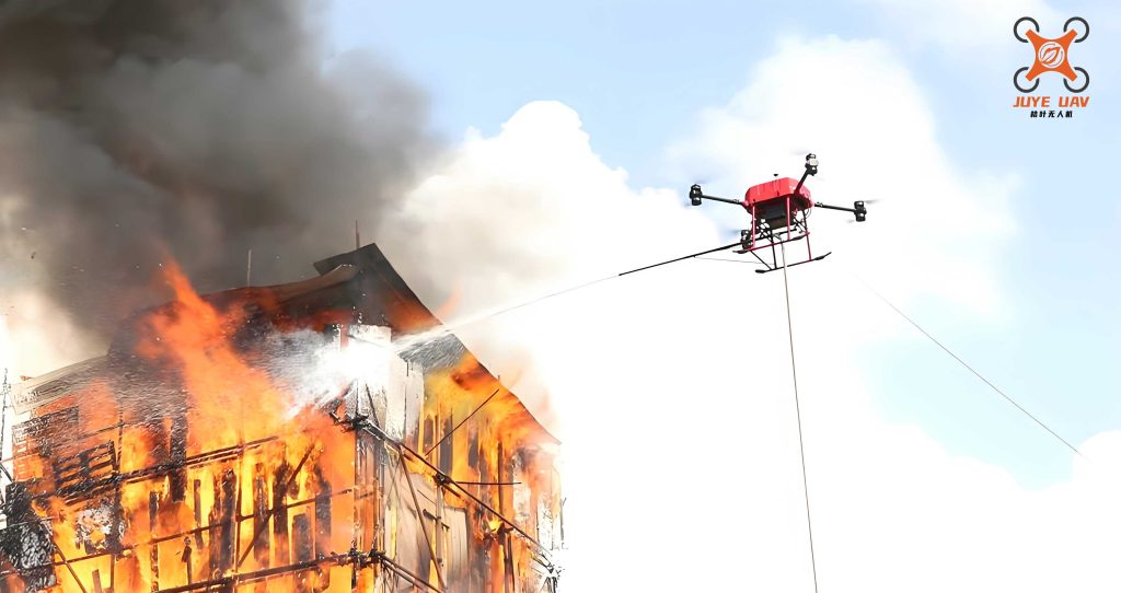
- Approach and Positioning: The fire UAV ascends rapidly to the approximate height of the trapped occupant’s window. Using its onboard flight controller and first-person view (FPV) from the visual system, the ground pilot navigates the UAV to a stable hover position approximately 2-3 meters from the building facade, aligning the delivery mechanism with the window.
- Aerial Interface: A lightweight, carbon-fiber extension boom (outrigger arm) is deployed from the UAV’s body. At its distal end, a retrieval lanyard with a large, brightly colored grip ring is temporarily secured. The pilot finely adjusts the hover to present this grip ring within arm’s reach of the trapped individual inside the window.
- Payload Transfer: Once visual confirmation (via the onboard camera) is received that the occupant has securely grasped the grip ring, the ground operator triggers the release mechanism. A specialized escape kit, weighing approximately 5 kg, is detached from the UAV’s undercarriage and descends a short, controlled distance, suspended by the lanyard now held by the occupant.
- Retrieval and Instruction: The fire UAV then gently maneuvers away from the building to a safer distance. The occupant pulls the escape kit into the room. Through the live video feed and a powerful onboard loudspeaker, rescue personnel on the ground provide real-time, step-by-step verbal instructions to calm the occupant and guide them in properly donning the descent harness and securing the device.
- Controlled Descent: Following the instructions, the occupant attaches the device to a secure anchor point inside the room and initiates a controlled, slow descent down the exterior wall to safety.
The technical specifications defining the capabilities of this integrated fire UAV system are summarized in the table below.
| Parameter | Specification |
|---|---|
| UAV Platform Type | Hexacopter (DJI Matrice 600 Pro) |
| Maximum Take-Off Weight (MTOW) | 17.5 kg |
| Rescue Payload Capacity (Escape Kit) | 5 kg (Standard) |
| Hover Endurance (with 5 kg payload) | ≥ 20 minutes |
| Maximum Service Ceiling | > 500 m |
| Maximum Ascent Speed | 7 m/s |
| Wind Resistance | Up to 12 m/s |
| Extension Boom Length | 2.5 m (Carbon Fiber) |
| Visual System | 1080p/30fps FPV Camera with Gimbal |
| Audio System | 100W Remote-Controlled Loudspeaker |
| Command & Control Range | ≥ 5 km (Video, Telemetry, Control) |
| Payload Release Mechanism | Servo-Actuated Remote Release |
Design of the Core Aerial Delivery System (ADS)
The Aerial Delivery System is the operational heart of the rescue fire UAV. Its design prioritizes reliability, safety for the recipient, and minimal disruption to the UAV’s flight dynamics. The ADS consists of four main components: the Extension Boom, the Payload Release Mechanism, the Retrieval Lanyard, and the Escape Kit.
1. Extension Boom: The boom must be long enough to bridge the safe hover distance from the building yet lightweight to avoid creating a significant, destabilizing moment. A 2.5-meter hollow carbon fiber tube was selected. Its high strength-to-weight ratio and stiffness minimize bending during flight. The boom is mounted via a quick-release clamp, allowing for easy attachment and removal for transport. The primary design consideration is the bending moment induced at the mount point due to the boom’s weight and any aerodynamic forces. The deflection $$ \delta $$ at the free end of a cantilever beam under a uniformly distributed load (its own weight) is given by:
$$ \delta = \frac{w L^4}{8 E I} $$
where $$ w $$ is the weight per unit length, $$ L $$ is the length (2.5 m), $$ E $$ is the modulus of elasticity of carbon fiber, and $$ I $$ is the area moment of inertia of the tube’s cross-section. Selecting a tube with sufficient $$ I $$ ensures deflection is negligible for precise positioning.
2. Payload Release Mechanism: This is a fail-safe, remotely actuated mechanism designed to cleanly and reliably disengage the escape kit. It employs a high-torque servo motor connected to a four-bar linkage system that retracts a retaining pin. The escape kit is suspended from a shackle connected to this pin. Upon command, the servo rotates, retracting the pin via the linkage and allowing the shackle (and kit) to fall free. The mechanism’s holding force must significantly exceed the static load of the kit to prevent accidental release, yet the actuation force must be within the servo’s capability. The required servo torque $$ \tau_{servo} $$ is calculated based on the linkage geometry and the friction force $$ F_{friction} $$ at the pin:
$$ \tau_{servo} = \frac{F_{friction} \cdot r_{effective}}{\eta} $$
where $$ r_{effective} $$ is the effective radius from the linkage design and $$ \eta $$ is the mechanism’s efficiency.
3. Retrieval Lanyard and Temporary Attachment: A high-strength, low-stretch kernmantle rope of specified length (e.g., 3 meters total) is used. One end is permanently fixed to the escape kit’s harness. The other end terminates in the large grip ring. For flight, the lanyard is routed along the extension boom and its midsection is temporarily secured to the boom using weak, frangible adhesive tape or a breakable thread. This ensures the lanyard does not swing during transit. When the kit is released, its weight easily breaks these temporary attachments, allowing it to fall freely until the rope is taut, held by the occupant. The length of the lanyard is critical: it must provide enough slack for a safe drop distance without generating a significant impulsive load when it snaps taut. The force $$ F_{snap} $$ on the occupant’s arm can be approximated by considering the kinetic energy of the falling kit being absorbed by the rope’s elasticity:
$$ \frac{1}{2} m v^2 \approx \frac{1}{2} k x^2 $$
where $$ m $$ is the kit mass, $$ v $$ is its velocity at the end of the drop, $$ k $$ is the effective spring constant of the rope/system, and $$ x $$ is the maximum stretch. Minimizing $$ v $$ (by minimizing initial drop height before the tape breaks) is key to keeping $$ F_{snap} $$ manageable.
4. Integrated Sensory and Communication Suite: The effectiveness of the fire UAV hinges on the ground operator’s situational awareness. A high-definition camera mounted on a stabilized gimbal provides a clear, real-time view of the occupant, the window, and the interaction with the grip ring. This visual feed is transmitted digitally to the ground control station. A separate, high-power (100W) loudspeaker module is mounted on the UAV’s frame. This allows rescue personnel to project clear, calming instructions and commands directly to the confused and potentially panicked occupant, guiding them through the retrieval and donning process.
Flight Dynamics and Stability Analysis
Integrating the ADS and its asymmetric extension boom introduces perturbations to the standard flight dynamics of the hexacopter. A rigorous analysis is required to ensure the fire UAV remains controllable throughout the mission profile, especially during the critical payload release phase. We define two primary coordinate systems for this analysis.
1. Coordinate Systems:
– **Earth-Fixed Frame $$ \{E\} $$:** Defined by axes $$ O_E X_E Y_E Z_E $$, with $$ Z_E $$ pointing upward (opposite gravity), $$ X_E $$ pointing North, and $$ Y_E $$ pointing West. This is an inertial frame.
– **Body-Fixed Frame $$ \{B\} $$:** Defined by axes $$ O_B X_B Y_B Z_B $$, fixed to the fire UAV’s chassis. $$ X_B $$ points forward (along the boom mounting axis in our design), $$ Y_B $$ points left, and $$ Z_B $$ points upward. The origin $$ O_B $$ is at the vehicle’s center of mass (CG).
The vehicle’s attitude is described by the Euler angles: roll ($$ \phi $$) about $$ X_B $$, pitch ($$ \theta $$) about $$ Y_B $$, and yaw ($$ \psi $$) about $$ Z_B $$. The rotation matrix $$ \mathbf{R}^B_E $$ that transforms a vector from the Earth frame to the Body frame is given by the sequence of rotations Z-Y-X (yaw, pitch, roll):
$$
\mathbf{R}^B_E =
\begin{bmatrix}
\cos\theta \cos\psi & \cos\theta \sin\psi & -\sin\theta \\
\sin\phi \sin\theta \cos\psi – \cos\phi \sin\psi & \sin\phi \sin\theta \sin\psi + \cos\phi \cos\psi & \sin\phi \cos\theta \\
\cos\phi \sin\theta \cos\psi + \sin\phi \sin\psi & \cos\phi \sin\theta \sin\psi – \sin\phi \cos\psi & \cos\phi \cos\theta
\end{bmatrix}
$$
The inverse transformation, from Body to Earth frame, is simply the transpose: $$ \mathbf{R}^E_B = (\mathbf{R}^B_E)^T $$.
2. Effect of the Asymmetric Payload: The mounted extension boom and the suspended escape kit create a combined mass $$ m_{payload} $$ located at a displacement $$ \mathbf{r}_p = [x_p, 0, z_p]^T $$ from the UAV’s nominal CG (assuming the boom is mounted along the $$ X_B $$ axis). This introduces two primary effects:
– A shift in the overall system’s CG.
– A constant gravitational moment (torque) about the CG that the flight controller must counteract.
The new combined CG $$ \mathbf{r}_{cg, total} $$ is calculated as:
$$ \mathbf{r}_{cg, total} = \frac{m_{uav} \cdot \mathbf{0} + m_{payload} \cdot \mathbf{r}_p}{m_{uav} + m_{payload}} $$
where $$ m_{uav} $$ is the mass of the UAV without payload, and we assume its CG is at the origin of the body frame.
The gravitational force vector in the Earth frame is $$ \mathbf{F}_g^E = [0, 0, (m_{uav}+m_{payload})g]^T $$. In the Body frame, it is:
$$ \mathbf{F}_g^B = \mathbf{R}^B_E \mathbf{F}_g^E $$
This force, acting at the combined CG $$ \mathbf{r}_{cg, total} $$, creates a moment $$ \boldsymbol{\tau}_g^B $$ about the body frame origin:
$$ \boldsymbol{\tau}_g^B = \mathbf{r}_{cg, total} \times \mathbf{F}_g^B $$
This moment has non-zero components primarily in the roll and pitch axes, requiring a constant corrective thrust differential from the motors to maintain level hover. The flight controller’s PID loops automatically generate these corrections based on IMU feedback.
3. Dynamics During Payload Release: The instantaneous release of the escape kit represents a significant dynamic disturbance. At the moment of release, two abrupt changes occur:
1. The total vehicle mass decreases by $$ m_{payload} $$.
2. The external moment $$ \boldsymbol{\tau}_g^B $$ vanishes instantly.
Let $$ \mathbf{T}_B $$ be the total thrust vector generated by the six rotors in the body frame just before release. For steady hover before release, the force and moment equilibria are:
$$ \sum \mathbf{F}^B: \quad \mathbf{T}_B + \mathbf{F}_g^B = \mathbf{0} $$
$$ \sum \boldsymbol{\tau}^B: \quad \boldsymbol{\tau}_{motors} + \boldsymbol{\tau}_g^B = \mathbf{0} $$
where $$ \boldsymbol{\tau}_{motors} $$ is the net moment generated by differential rotor thrusts.
At the instant after release ($$ t^+ $$), the mass and CG revert to the UAV’s baseline, but the motor commands (thrust $$ \mathbf{T}_B $$ and moment $$ \boldsymbol{\tau}_{motors} $$) are still at their pre-release values for a short period due to controller latency. This creates temporary imbalances:
$$ \sum \mathbf{F}^B(t^+): \quad \mathbf{T}_B + \mathbf{F}_g^{B,new} \neq \mathbf{0} \quad \text{where } \mathbf{F}_g^{B,new} = \mathbf{R}^B_E [0, 0, m_{uav}g]^T $$
$$ \sum \boldsymbol{\tau}^B(t^+): \quad \boldsymbol{\tau}_{motors} + \mathbf{0} \neq \mathbf{0} $$
The force imbalance causes a vertical and translational acceleration. The moment imbalance, now lacking the counteracting $$ \boldsymbol{\tau}_g^B $$, causes a sudden rotational acceleration. The agility and high update rate of the modern flight controller are essential to quickly sense these accelerations via the IMU and compute new, stable motor commands within milliseconds. The robustness of the chosen hexacopter platform to such payload-drop disturbances is a key selection criterion for this fire UAV application.
Experimental Validation and Field Testing
Comprehensive field tests were conducted in collaboration with municipal fire rescue agencies to validate the performance, reliability, and safety of the fire UAV system. The tests simulated real-world high-rise rescue scenarios, focusing on the complete operational workflow.
Test Setup and Protocol: A multi-story training building was used. A test subject acted as the “trapped occupant” on various floors. The fire UAV, loaded with a 5 kg dummy escape kit, was deployed from a ground station. The following key performance indicators (KPIs) were evaluated: Hover Stability (with and without boom/payload), Positioning Accuracy, Reliability of Payload Release, Clarity of Audio-Visual Link, and Overall Mission Completion Time.
| Test Phase / Metric | Observation / Measurement | Result & Assessment |
|---|---|---|
| Deployment & Ascent | Time to climb to 50m altitude from launch. | ~12 seconds. Confirmed rapid response capability of the fire UAV. |
| Stable Hover with Payload | Positional drift (RMS) over 60 seconds at 30m altitude in light wind (<5 m/s). | Vertical: ±0.15m; Horizontal: ±0.25m. Stability deemed excellent for precise delivery. |
| Boom Extension Effect | Observable attitude correction and controller activity after boom deployment. | Controller successfully compensated for induced rolling moment. No pilot intervention required. |
| Visual Guidance | FPV video quality and latency at 100m range. | 1080p/30fps stream with <200ms latency. Provided clear view of grip ring and occupant’s hand for precise positioning. |
| Payload Release | Reliability of servo mechanism and clean separation of kit. | 10/10 successful releases. Kit fell cleanly without entanglement. The sudden loss of mass caused a minor, brief upward jerk which the controller stabilized within ~1 second. |
| Lanyard Dynamics | Force felt by “occupant” when catching the falling kit. | Perceived as a firm but manageable tug. Calculated snap force was within safe limits for an average adult. |
| Audio Communication | Intelligibility of speech from loudspeaker at 30m distance with ambient noise. | Instructions were clearly audible and understandable to the “occupant” inside the simulated environment. |
| End-to-End Mission Time | Time from UAV launch to “occupant” pulling kit into window. | Average time: 3 minutes 45 seconds. Demonstrates the potential for drastically reduced time-to-aid compared to traditional methods. |
Analysis of Results: The experimental data confirms the feasibility of the core concept. The fire UAV platform demonstrated sufficient power and control authority to handle the asymmetric load and the dynamic release event. The integrated Aerial Delivery System performed its function reliably. The sensory feedback provided to the ground operator was of high quality, enabling informed decision-making. The most critical finding was the system’s ability to establish a physical connection with a trapped individual in a safe and controlled manner, which is the fundamental requirement for this class of rescue.
Discussion and Conclusion
This work presents a comprehensive engineering solution to a specific and challenging gap in high-rise emergency response. The designed fire UAV system moves beyond the roles of observer or suppressor to become an active, life-delivering agent. By integrating a mechanically simple yet effective Aerial Delivery System with robust sensory and communication links, the platform enables a new operational procedure for fire rescue services.
The success of the system hinges on several key design principles validated through modeling and experiment:
1. **Stability-Centric Design:** Every component, especially the extension boom, was analyzed for its impact on flight dynamics. The chosen materials and geometry minimized disruptive moments.
2. **Sequenced Human-Machine Interaction:** The procedure is designed to leverage human judgment (via video) for critical steps like confirming grip, while automating reliable mechanical actions (release).
3. **Redundancy and Safety in Interaction:** The weak-link attachment of the lanyard and its calculated length ensure the physical transfer of force to the occupant is controlled and safe, decoupling it from the UAV’s flight stability.
4. **Integration Over Novelty:** The system effectively integrates proven, reliable components (commercial UAV, servo, camera, speaker) into a novel workflow, enhancing overall system reliability.
Future Work and Potential Enhancements: While the prototype system is functional, several avenues for improvement exist. Future iterations of the fire UAV could incorporate:
– **Automated Positioning:** Using machine vision to automatically identify a window and align the delivery boom, reducing pilot workload.
– **Dual-Payload Capability:** Carrying a small fire suppression agent (e.g., a compact extinguisher ball) alongside the escape kit for very early-stage compartment fire control upon delivery.
– **Advanced Descent Devices:** Integration of a “smart” descent controller within the escape kit that can auto-brake or adjust speed based on the user’s weight or descent angle.
– **Swarm Coordination:** Deploying multiple fire UAVs in a coordinated manner—one for delivery, one for overwatch/lighting, and one for wider situational awareness of the fire front.
In conclusion, the development and testing of this specialized fire UAV demonstrate a viable and promising approach to mitigating one of the most perilous scenarios in urban firefighting. By delivering the means of self-rescue directly to those in need within minutes, this technology has the potential to significantly reduce casualties in high-rise fire events, irrespective of the timeline for conventional fire suppression or external rescue. It represents a meaningful step forward in leveraging robotic systems to address the persistent “pain points” in public safety and disaster response.