
The continuous pursuit of efficiency and precision in modern agriculture has driven significant innovation in crop protection technologies. Among these, the integration of Unmanned Aerial Vehicles (UAVs) with advanced spraying techniques represents a paradigm shift. This article presents a comprehensive, first-person study on the design, implementation, and testing of a dedicated electrostatic spraying system for multi-rotor agricultural UAVs. The primary objective is to enhance the deposition efficiency and reduce drift of pesticide droplets, thereby improving the overall effectiveness of aerial plant protection operations.
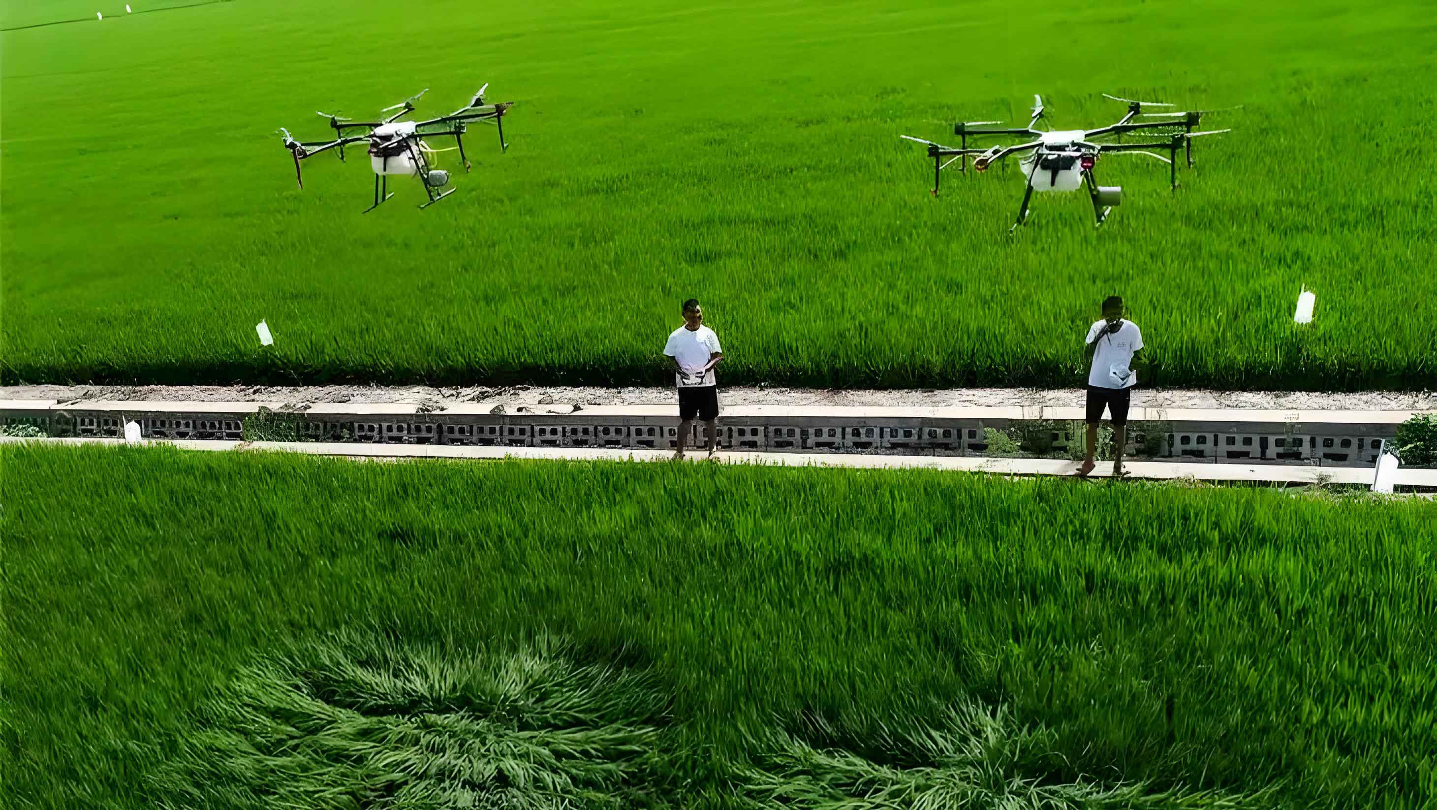
The core challenge in aerial spraying lies in achieving sufficient droplet deposition on target surfaces, particularly on the undersides of leaves. Conventional aerial spray systems often suffer from significant drift and uneven coverage. Electrostatic charging of spray droplets induces a charge on them, promoting their attraction to the usually grounded or oppositely charged plant surfaces. This Coulombic force can significantly improve adhesion, wraparound effect, and deposition uniformity. When mounted on a versatile agricultural UAV, this technology promises a highly targeted and efficient application method. The design of such a system must account for the unique constraints of the multi-rotor platform, including limited payload capacity, power availability, and the complex downwash airflow generated by the propellers.
1. System Architecture and Design Philosophy
The designed electrostatic spraying system for the agricultural UAV is based on the principle of induction charging. This method was selected for its relative simplicity, safety, and effectiveness in generating a stable charge on conductive liquids like water-based pesticide solutions. The complete system integrates seamlessly with the airframe and existing flight control systems of a commercial multi-rotor agricultural UAV. The primary components include the electrostatic spray nozzle assembly, a high-voltage generator, a liquid delivery and precise flow control module, and the necessary power distribution units. A summary of the system’s key components and their specifications is presented in Table 1.
| Component | Type/Specification | Key Function |
|---|---|---|
| Spray Platform | Multi-Rotor Agricultural UAV (W730S model) | Carries the spray system, provides flight stability and navigation. |
| Spray Nozzle | Custom-designed Inductive Centrifugal Nozzle | Atomizes liquid and imparts an electrostatic charge to droplets. |
| High-Voltage Generator | Compact, adjustable (0-10 kV), 12V DC input | Supplies high voltage to the induction electrode. |
| Flow Control Module | PID-based algorithm with centrifugal pump & flow sensor | Maintains a stable and speed-dependent spray application rate. |
| Charge Measurement Device | Mesh Target System with precision ammeter | Measures the charge-to-mass ratio (CMR) of the spray cloud. |
The system operates as follows: The flight controller of the agricultural UAV communicates the real-time ground speed to the spraying control module. This module calculates the required theoretical flow rate and adjusts the pump speed accordingly. Simultaneously, the high-voltage generator is activated, applying a potential to the induction ring surrounding the nozzle. As the pesticide solution is atomized by the spinning disc of the centrifugal nozzle and passes through the intense electric field near the induction ring, it becomes charged. The charged droplet cloud is then carried downward by the propeller downwash towards the crop canopy.
2. Core Component Design and Theoretical Foundation
2.1 Inductive Centrifugal Electrostatic Nozzle
The heart of the system is the custom-designed inductive centrifugal nozzle. Centrifugal atomization was chosen for its ability to produce a consistent, fine droplet spectrum suitable for aerial application with an agricultural UAV. The nozzle assembly consists of a high-speed DC motor, a rotary atomizer disc, an induction electrode (ring), and an insulating mount.
The induction charging process can be described theoretically. When a high voltage \( V \) is applied to the induction ring, an electric field \( \vec{E} \) is established in the space between the ring and the grounded nozzle body (and the emerging liquid film). The magnitude of this field near the point of droplet formation is critical. As the conductive liquid breaks up into droplets at the edge of the spinning disc, they traverse this electric field. This induces a charge \( q \) on each droplet. For a perfectly conductive liquid, the charge acquired just before detachment can be related to the droplet’s surface area and the local electric field strength. A simplified model for the charge on a droplet formed in an inductive field is given by:
$$ q = k \cdot \pi \cdot d^2 \cdot \epsilon_0 \cdot E $$
where \( d \) is the droplet diameter, \( \epsilon_0 \) is the permittivity of free space, \( E \) is the electric field strength at the point of detachment, and \( k \) is a dimensionless constant dependent on geometry and fluid properties. The induction ring is positioned 20 mm below the atomizing edge and is made of corrosion-resistant stainless steel. The insulating mount is fabricated from nylon PA6T, chosen for its excellent chemical resistance and dielectric strength, ensuring no leakage of the high voltage.
2.2 High-Voltage Circuit Configuration
The high-voltage generator is a critical subsystem. For induction charging to work effectively, a closed circuit must be established. The negative terminal of the generator is connected to the metallic frame of the agricultural UAV, which acts as a virtual ground due to its large capacitance relative to the air. The positive terminal is connected to the induction ring. This setup creates the necessary electric field between the ring (high positive potential) and the nearby grounded liquid surface. An alternative configuration with reversed polarity is also possible and was tested; the fundamental charging mechanism remains the same, with the polarity of the droplet charge being reversed.
2.3 Precision Spray Flow Control Module
Maintaining a constant application rate per unit area is essential for effective and economical pest control, regardless of the agricultural UAV‘s flight speed. A closed-loop feedback control system was implemented. The theoretical flow rate \( L_{theory} \) (in mL/min) is calculated based on the desired application volume per hectare \( App_{rate} \) (L/ha), the swath width \( W \) (m), and the current ground speed \( v \) (m/s):
$$ L_{theory} = \frac{App_{rate} \times W \times v \times 60}{10000} $$
A PID (Proportional-Integral-Derivative) control algorithm was employed to minimize the error \( e(t) \) between the theoretical flow rate and the actual flow rate \( L_{actual} \) measured by an in-line flow sensor. The control signal \( u(t) \) sent to the pump’s electronic speed controller (ESC) is determined by:
$$ u(t) = K_p e(t) + K_i \int_0^t e(\tau) d\tau + K_d \frac{de(t)}{dt} $$
where \( K_p \), \( K_i \), and \( K_d \) are the proportional, integral, and derivative gain constants, respectively. These constants were tuned via simulation in Simulink prior to field testing to ensure a fast and stable response without overshoot, crucial for the dynamic operation of an agricultural UAV.
3. Experimental Methodology and Measurement Apparatus
To validate the performance of each subsystem and the integrated whole, a series of controlled experiments were designed and conducted.
3.1 Spray Flow Stability Test
The objective was to verify that the PID-controlled module could maintain a stable flow rate across the operational speed range of the agricultural UAV. Tests were conducted at five different simulated flight speeds (1-5 m/s). For each set speed, the system was activated, and the entire spray output from a single nozzle over a fixed time period was collected in a container. The mass of the collected liquid was measured using a precision balance, and the volumetric flow rate was calculated. This was repeated five times per speed setting. Two key metrics were derived:
1. Flow Rate Error \( P_L \): The deviation of the average measured flow from the theoretical target.
$$ P_L = \frac{| \bar{L} – L_{theory} |}{L_{theory}} \times 100\% $$
2. Average Relative Deviation \( K_L \): A measure of the flow rate stability (precision) during repeated tests.
$$ K_L = \frac{ \sum_{i=1}^{N} | L_i – \bar{L} | }{N \cdot \bar{L}} \times 100\% $$
where \( L_i \) is an individual measurement, \( \bar{L} \) is the mean of N measurements (N=5).
3.2 Charge-to-Mass Ratio (CMR) Measurement
The charge-to-mass ratio is the definitive metric for evaluating the electrostatic charging performance of the agricultural UAV system. A specialized measurement apparatus based on the “mesh target” method was designed and constructed. The device consists of three stacked, graded stainless steel meshes (400, 250, and 100 mesh) connected electrically in series to a high-precision microammeter and then to ground. The spray cloud from the charged nozzle is directed onto this assembly. As charged droplets impact the meshes, they transfer their charge, which flows as a current \( I \) (µA) through the ammeter. The mass \( m \) (kg) of the spray liquid collected in a shielded container beneath the meshes over a known time \( t \) (s) is measured. The volume is converted to mass assuming a density of ~1000 kg/m³ for the spray mixture. The average CMR \( A_q \) is calculated as:
$$ A_q = \frac{Q}{m} = \frac{I \cdot t}{m} \quad \text{(units: C/kg)} $$
A high CMR indicates effective charging. The stability of the measurement system itself was assessed by calculating the average relative deviation \( k_x \) of multiple CMR readings under identical conditions. Experiments were conducted at increasing induction voltages from 0 to 10 kV in 2 kV increments, with the spray height fixed at 0.5 m. The applied voltage was verified using a high-voltage probe and multimeter.
4. Results, Analysis, and Discussion
4.1 Performance of the Flow Control System
The results from the flow stability tests are consolidated in Table 2. The PID gains obtained from simulation (\(K_p = 66.0\), \(K_i = 2.4\), \(K_d = 435.6\)) proved highly effective in the physical system.
| UAV Speed (m/s) | Theoretical Flow (mL/min) | Mean Measured Flow, \(\bar{L}\) (mL/min) | Flow Error, \(P_L\) (%) | Avg. Relative Deviation, \(K_L\) (%) |
|---|---|---|---|---|
| 1 | 220 | 223.6 | 1.64 | 1.20 |
| 2 | 320 | 326.1 | 1.90 | 0.74 |
| 3 | 420 | 425.1 | 1.21 | 0.72 |
| 4 | 520 | 516.4 | 0.69 | 0.50 |
| 5 | 620 | 614.4 | 0.90 | 0.45 |
Analysis of Table 2 confirms the excellent performance of the control module. The flow error \(P_L\) remained below 2% across all speed settings, demonstrating high accuracy. Furthermore, the average relative deviation \(K_L\) was consistently low (≤1.2%), indicating very stable flow output with minimal fluctuation during repeated operations. This precision is vital for ensuring a uniform application rate in the field, a key advantage offered by a well-instrumented agricultural UAV.
4.2 Electrostatic Charging Performance
The results from the CMR measurement experiments are presented in Table 3 and graphically in Figure 1 (conceptual description: a plot of CMR vs. Charging Voltage). The measurement apparatus showed good stability, with relative deviations \(k_x\) below 9% for all voltages, validating its reliability.
| Charging Voltage (kV) | Mean CMR, \(A_q\) (mC/kg) | CMR Relative Deviation, \(k_x\) (%) |
|---|---|---|
| 0 (Control) | ~0 | N/A |
| 2 | 0.19 | 3.21 |
| 4 | 0.34 | 3.12 |
| 6 | 0.50 | 3.44 |
| 8 | 0.59 | 5.65 |
| 10 | 0.58 | 8.92 |
The data reveals a clear and significant trend: the CMR increases with the applied induction voltage up to approximately 8 kV. This relationship is expected, as a higher voltage creates a stronger electric field \(E\), which, according to the theoretical model, leads to a higher induced charge \(q\) on the droplets. The measured CMR of 0.59 mC/kg at 8 kV is within the effective range reported for agricultural electrostatic spraying (typically 0.1 to 2.0 mC/kg). The saturation or slight decrease observed at 10 kV is a known phenomenon in induction charging. It can be attributed to several factors: increased corona discharge at the sharp edges of the induction ring at very high voltages, which wastes energy and can ionize the air, creating opposing charges; or a physical limit related to the dielectric strength of the air and the finite conductivity of the liquid. This finding is crucial for optimizing the system on an agricultural UAV, as it identifies the operational voltage (8 kV) that maximizes charging efficiency without unnecessary power consumption or potential instability.
The successful measurement of a significant CMR unequivocally proves that the designed inductive centrifugal nozzle, integrated into the agricultural UAV platform, is fully functional and capable of imparting a substantial electrostatic charge to the spray droplets.
5. System Integration and Operational Considerations for Agricultural UAVs
Integrating an electrostatic system onto a multi-rotor agricultural UAV involves careful engineering beyond component design. The additional mass of the high-voltage generator, wiring, and reinforced nozzles must be accounted for within the platform’s payload budget. The electrical system must be shielded to prevent electromagnetic interference (EMI) with the sensitive flight controller and GPS receivers. Furthermore, the positioning of the nozzles relative to the propellers is critical. The strong downwash airflow is a double-edged sword: it helps to drive droplets toward the canopy and reduce drift, but it may also disrupt the trajectory of the very fine, charged droplets or promote premature evaporation. Our design places the nozzles directly beneath the propeller plane to maximize beneficial interaction with the downwash.
The operational workflow for the agricultural UAV pilot is streamlined. After filling the tank and performing pre-flight checks, the operator selects the desired application rate on the ground control station. The flight controller and spray controller synchronize automatically. Upon initiating the spray mission, the high-voltage system is energized, and the flow control module maintains the correct rate. This level of automation is essential for making advanced electrostatic technology practical and user-friendly in real-world farming scenarios.
6. Conclusion and Future Perspectives
This study has successfully detailed the development and validation of a functional electrostatic spraying system specifically for a multi-rotor agricultural UAV. The system centers on a custom inductive centrifugal nozzle capable of charging spray droplets. A precision PID-based flow control module was implemented and proven to regulate spray output with an error of less than 2% and high stability across the operational speed range. A robust mesh-target measurement apparatus was designed, which confirmed the system’s charging capability, demonstrating a peak charge-to-mass ratio of 0.59 mC/kg at an optimal induction voltage of 8 kV.
The integration of this technology onto a versatile agricultural UAV platform holds considerable promise for the future of precision agriculture. The demonstrated technical feasibility is the first critical step. Future work must focus on agronomic validation. Comprehensive field trials are needed to quantify the improvement in deposition efficiency, canopy penetration, and wraparound on critical crop surfaces (e.g., underside of leaves) compared to non-electrostatic aerial spraying. The impact on biological efficacy—the actual control of pests and diseases—must be evaluated. Furthermore, studies on the reduction of off-target drift and environmental loading are essential. System optimization will also continue, exploring lighter materials, more efficient high-voltage circuits, and advanced control algorithms that can adapt to real-time changes in canopy density. As these advancements converge, the intelligent, electrostatic-charging agricultural UAV is poised to become a cornerstone of sustainable, efficient, and highly targeted crop protection strategies worldwide.