
The rapid adoption of agricultural UAVs for crop protection has revolutionized precision agriculture. These systems offer unparalleled efficiency, operational flexibility, superior spray application quality, and excellent adaptability to diverse terrain. A critical component influencing the efficacy of spray applications from an agricultural UAV is the complex downwash airflow field generated by its rotors. This flow field is responsible for atomizing liquid, transporting droplets toward the canopy, and facilitating their penetration and deposition. However, during real-world operation, an agricultural UAV is seldom in a perfect hover. Its forward flight creates a relative incoming flow, and it is invariably subjected to environmental crosswinds. These wind conditions significantly disrupt the downwash structure, leading to flow field distortion, lateral and rearward lag, increased droplet drift, and ultimately, uneven chemical deposition. This compromises application effectiveness, poses environmental risks, and complicates automated flight path planning. Therefore, a deep understanding of how incoming flow and crosswinds influence the downwash airflow field is paramount for optimizing the performance of agricultural UAVs.
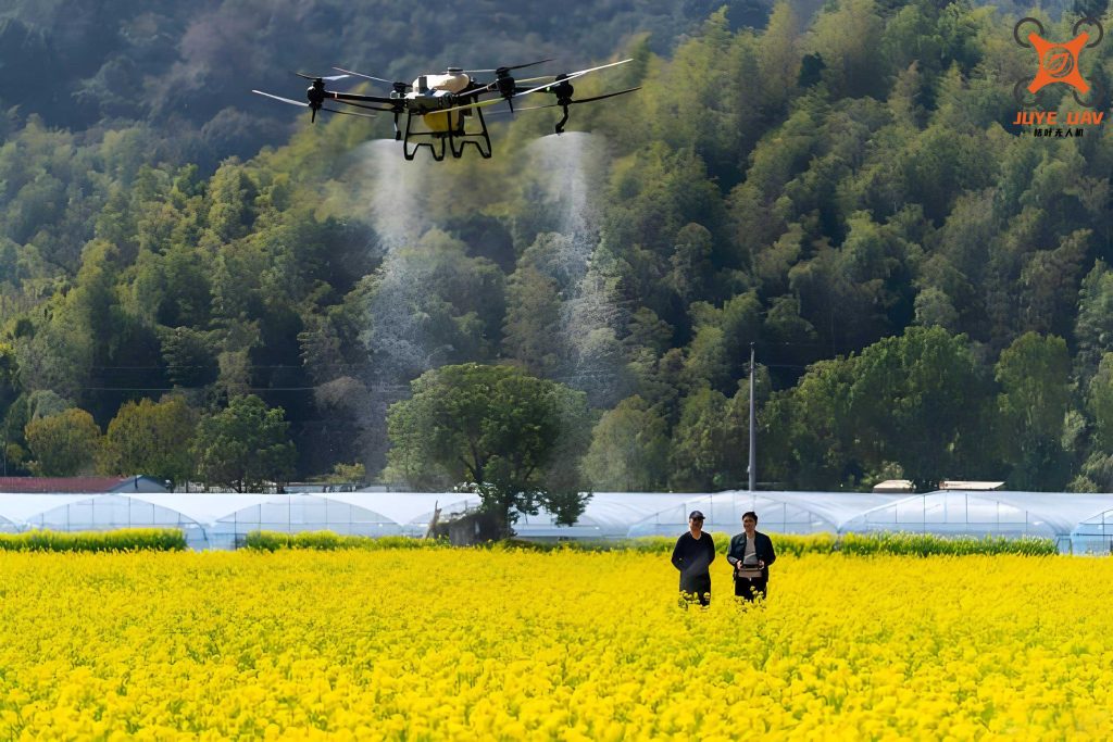
Existing research has extensively covered droplet deposition, drift, and spray swath for agricultural UAVs. While field measurements and advanced techniques like Particle Image Velocimetry (PIV) provide valuable insights, they often involve long cycles, high resource consumption, and limitations in capturing the complete, instantaneous flow field structure. Computational Fluid Dynamics (CFD) presents a powerful alternative. Traditional CFD methods, though widely used, face challenges with mesh generation and reconstruction for complex moving boundaries like rotating rotors. The Lattice Boltzmann Method (LBM), a mesoscopic particle-based approach, excels in simulating flows with complex boundaries and moving objects without the need for conventional mesh generation, making it particularly suitable for studying the downwash of an agricultural UAV. This study employs an LBM-based approach with a Wall-Adapting Local Eddy-viscosity (WALE) turbulence model to numerically investigate the downwash flow field of a single-rotor agricultural UAV under the combined influence of forward incoming flow and side winds. The findings aim to establish a foundation for understanding subsequent droplet dynamics and provide guidance for practical spraying operations.
Theoretical Framework and Numerical Methodology
1. The Lattice Boltzmann Method (LBM) Fundamentals
Unlike traditional CFD methods that solve the macroscopic Navier-Stokes equations, the LBM operates at a mesoscopic scale by tracking the evolution of particle distribution functions on a discrete lattice. For three-dimensional external flow simulations, the D3Q27 lattice model is typically employed, discretizing the velocity space into 27 discrete velocity vectors. The core of the LBM is the Lattice Boltzmann Equation (LBE), which is discretized on the lattice as:
$$f_i(\mathbf{x} + \mathbf{e}_i \Delta t, t + \Delta t) = f_i(\mathbf{x}, t) + \Omega_i(\mathbf{x}, t)$$
where \(f_i\) is the particle distribution function in the \(i\)-th velocity direction, \(\mathbf{e}_i\) is the discrete velocity vector, \(\Delta t\) is the time step, and \(\Omega_i\) is the collision operator. A common and simple collision model is the Bhatnagar-Gross-Krook (BGK) approximation:
$$\Omega_i = -\frac{1}{\tau} (f_i – f_i^{eq})$$
Here, \(\tau\) is the dimensionless relaxation time related to the fluid kinematic viscosity, and \(f_i^{eq}\) is the local equilibrium distribution function, a function of local fluid density and velocity. Through the Chapman-Enskog expansion, this kinetic formulation can be shown to recover the incompressible Navier-Stokes equations at the macroscopic scale. The key advantage for simulating an agricultural UAV is that complex moving boundaries, such as rotating blades, can be handled with relative ease compared to mesh-based methods.
2. Turbulence Modeling: The WALE SGS Model
To accurately capture the highly turbulent and vortical nature of the downwash flow field from an agricultural UAV, a proper turbulence model is essential. In this study, the Wall-Adapting Local Eddy-viscosity (WALE) subgrid-scale (SGS) model is used within the LBM framework. The WALE model calculates the turbulent eddy viscosity \(\nu_t\) based on the traceless symmetric part of the square of the velocity gradient tensor, allowing it to correctly reproduce the asymptotic behavior of turbulent boundary layers and handle near-wall flows effectively. The model is defined as:
$$\nu_t = (\Delta)^2 \frac{(S_{ij}^d S_{ij}^d)^{3/2}}{(S_{ij} S_{ij})^{5/2} + (S_{ij}^d S_{ij}^d)^{5/4}}$$
where \(\Delta = C_w V^{1/3}\) is the filter width (\(C_w\) is a constant, typically 0.325, and \(V\) is the local cell volume). \(S_{ij}\) is the strain rate tensor of the resolved flow:
$$S_{ij} = \frac{1}{2} \left( \frac{\partial v_i}{\partial x_j} + \frac{\partial v_j}{\partial x_i} \right)$$
and \(S_{ij}^d\) is the traceless symmetric part of the square of the velocity gradient tensor \(g_{ij} = \partial v_i / \partial x_j\):
$$S_{ij}^d = \frac{1}{2} (g_{ij}^2 + g_{ji}^2) – \frac{1}{3} \delta_{ij} g_{kk}^2$$
This model is well-suited for the separated flows and strong vortices present in the wake of an agricultural UAV rotor.
3. Wind Vector Synthesis and Simulation Strategy
Simulating a moving agricultural UAV in a large domain is computationally expensive. A more efficient strategy, grounded in the principle of relativity, is employed. The agricultural UAV is held stationary, and the combined effects of its forward motion and environmental wind are introduced as inlet boundary conditions on the computational domain. This is achieved through wind vector synthesis. The effective wind vector \(\mathbf{V_{eff}}\) acting on the stationary UAV model is the vector sum of the forward flight velocity \(\mathbf{V_f}\) (acting opposite to the UAV’s intended travel direction) and the environmental crosswind \(\mathbf{V_c}\).
$$\mathbf{V_{eff}} = \mathbf{V_f} + \mathbf{V_c}$$
If the UAV’s forward direction is along the negative Z-axis and a crosswind blows along the positive X-axis, the inlet velocity components are set as \(V_x = V_{c}\), \(V_y = 0\), \(V_z = -V_{f}\). This approach successfully replicates the relative airflow experienced by an agricultural UAV in forward flight under windy conditions.
4. Computational Setup and Parameters
The numerical study is based on a full-scale model of a representative single-rotor, gasoline-powered agricultural UAV. The main rotor diameter is 2.15 m, and the fuselage is simplified, excluding the tail boom and landing gear to reduce complexity. The computational domain is a large rectangular wind tunnel with dimensions 20 m (X) × 5 m (Y) × 20 m (Z). The ground is modeled as a no-slip wall. The UAV is positioned within the domain such that the rotor hub is at coordinates (X=-5m, Y=H, Z=-5m), where H is the flight height above ground.
To balance computational accuracy and cost, a multi-level grid refinement strategy is used. The base resolution for the entire domain is set, while significantly finer resolution is applied adaptively to regions of interest: the fuselage, the rotating rotor blades, and the anticipated vortex wake trajectories. The WALE turbulence model is applied throughout the domain. A series of simulations are conducted to systematically analyze the effects. The parameters are summarized in the table below.
| Parameter Category | Values/Specifications |
|---|---|
| Flight Height (H) | 1.5 m, 2.5 m, 3.0 m |
| Forward Flight Speed (Vf) | 1 m/s, 3 m/s, 5 m/s, 7 m/s |
| Crosswind Speed (Vc) | 0 m/s, 1 m/s, 3 m/s, 5 m/s, 7 m/s |
| Turbulence Model | Wall-Adapting Local Eddy-viscosity (WALE) |
| Numerical Method | Lattice Boltzmann Method (LBM) |
| Domain Boundaries | Velocity Inlet (with specified wind vector), Pressure Outlet, Ground (Wall) |
Analysis of Downwash Flow Field Under Forward Flight (No Crosswind)
1. Overall Flow Structure and Vortex Dynamics
Simulations of the single-rotor agricultural UAV in forward flight without crosswind reveal a complex interaction between the rotor-induced downwash and the incoming flow. At low forward speeds (e.g., 1 m/s and 3 m/s), the downwash structure remains relatively similar to the hover case after impinging on the ground. However, a distinct “ground vortex” forms in front of the UAV. This vortex interacts with the incoming flow, leading to irregular distortions and an early transition to turbulent flow in that region. As the forward speed increases to 5 m/s and 7 m/s, the influence of the incoming flow becomes dominant, causing a pronounced backward tilting or “lag” of the entire downwash field. The top-down view of the flow evolves from a roughly circular shape to a narrowed, fan-like structure.
A key observation is the development of asymmetric spiral tip vortices in the wake. This asymmetry arises from the differential relative velocity at the advancing and retreating sides of the rotor disc. For a rotor with rotational tip speed \(V_{tip}\), the effective speed at the blade tip moving into the wind (advancing side) is \(V_{tip} + V_f\), while on the opposite side (retreating side) it is \(V_{tip} – V_f\). At higher forward speeds, this difference becomes significant, leading to varied vortex shedding strength and trajectory on each side, resulting in an asymmetric wake pattern. These strong, spiraling tip vortices are a primary mechanism for droplet entrainment and can contribute to spray drift and uneven deposition patterns for the agricultural UAV.
2. Effect of Forward Speed on Flow Field Geometry and Lag
The forward speed has a dramatic impact on the inclination and deformation of the downwash flow field. At a constant flight height of 2.5 m, as the forward speed increases from 1 m/s to 7 m/s, the downwash plume tilts progressively backward. The lag distance and inclination angle increase non-linearly with speed. A critical finding is that at a forward speed of 7 m/s, a “secondary deflection” occurs. This is attributed to the complete dissipation of the forward ground vortex effect, which at lower speeds provides some resistance to the incoming flow. With this stabilizing effect gone, the downwash is fully dominated by the relative wind, leading to an extreme tilt angle. This severe lag implies that droplets released from the spray system will land significantly behind the UAV’s position, causing misapplication and increasing the potential for off-target drift in the presence of any additional environmental wind.
Interestingly, the flow analysis reveals a mechanism contributing to the wind resistance of the agricultural UAV. The rotor generates tip vortices that have a rotational component outward on the front and rear of the disc. The incoming forward flow directly opposes the rotational direction of the front vortex, leading to a local velocity cancellation effect. This interaction reduces the effective outward flow velocity on the windward side, enhancing the stability of the spray cloud in mild wind conditions.
| Forward Speed (m/s) | Flow Field Shape (Top View) | Primary Lag Angle | Key Flow Features | Implication for Spray |
|---|---|---|---|---|
| 1 | Near-Circular | ~0° | Formation of a forward ground vortex. | Minimal lag, deposition close to UAV path. |
| 3 | Slightly Elongated | ~30° | Ground vortex interacts with incoming flow. | Moderate lag begins. |
| 5 | Fan-shaped, Asymmetric Wake | ~52° | Pronounced lag, clear asymmetric spiral tip vortices. | Significant droplet lag, risk of entrainment in vortices. |
| 7 | Highly Distorted, Narrow Plume | ~71° (with secondary deflection) | Ground vortex vanishes, wake fully dominated by relative wind. | Severe lag and distortion, high drift potential. |
3. Velocity Profile and Distribution
Examining the velocity magnitude distribution at a plane near the ground provides insight into how the agricultural UAV distributes airflow energy. Under forward flight, the classic “bell-shaped” profile observed in hover transforms into a distinctive “M-shaped” profile. This profile is characterized by two velocity peaks symmetrically located on either side of the centerline, with a lower velocity region directly beneath and slightly behind the rotor hub.
The forward speed critically modulates this “M” profile. At a constant flight height, as forward speed increases:
- The lateral distance between the two velocity peaks decreases, meaning the high-speed regions become closer together.
- The peaks themselves shift further away from the rotor axis centerline.
- The entire velocity field translates backward, following the overall lag of the flow.
This indicates that changing the forward speed of the agricultural UAV does not necessarily improve droplet distribution uniformity; it primarily shifts the region of highest aerodynamic energy. Notably, at the highest simulated speed of 7 m/s, the coherent “M” profile breaks down as the flow becomes highly chaotic and less organized, which is undesirable for controlled spray application.
The velocity \(V\) at a point (x,z) behind the UAV can be conceptually related to forward speed \(V_f\) and rotor thrust \(T\) through an empirical relation suggested by the flow structure:
$$V(x,z) \approx f(T, V_f, H) \cdot \left[ \exp\left(-\frac{(z – z_{peak}(V_f))^2}{\sigma_z^2}\right) + \exp\left(-\frac{(z + z_{peak}(V_f))^2}{\sigma_z^2}\right) \right]$$
where \(z_{peak}\) is the peak location (increasing with \(V_f\)), and \(\sigma_z\) is a spread parameter (decreasing with \(V_f\)).
Analysis of Downwash Flow Field Under Combined Forward Flight and Crosswind
1. Flow Structure Deflection and Deformation
The introduction of a crosswind leads to a lateral deflection of the entire downwash flow field of the agricultural UAV. At a constant forward speed (e.g., 5 m/s) and flight height (2.5 m), as the crosswind speed increases from 1 m/s to 7 m/s, the downwash plume deflects laterally (downwind) at an increasing angle. The flow structure angle (the angular width of the plume) simultaneously decreases. The originally symmetric “U-shaped” or “fan-shaped” ground flow pattern becomes skewed. The edge of the flow on the windward side becomes sharper, while the leeward side expands. Despite this lateral shift and skewing, the fundamental “U-shaped” velocity structure observed in the no-crosswind forward flight case is preserved; it is merely translated and rotated. This persistent structure indicates that the rotor’s influence remains the dominant organizing feature of the near-field flow, even as it is advected by the crosswind.
2. Quantitative Analysis of Flow Field Offset
To quantify the effect, the lateral (X-axis) and longitudinal (Z-axis) offsets of the downwash footprint are measured relative to a point directly below the rotor hub. The lateral offset \(\Delta X\) shows a strong, approximately quadratic dependence on crosswind speed \(V_c\) for a given forward speed \(V_f\). This relationship can be expressed as:
$$\Delta X = a V_c^2 + b V_c + c$$
where coefficients \(a\), \(b\), and \(c\) depend on the forward flight speed \(V_f\). For instance, at \(V_f = 1\) m/s, the offset is smaller and follows one quadratic trend, while at \(V_f = 5\) m/s, it follows another with a larger linear coefficient, indicating a greater sensitivity to crosswind at higher forward speeds. The longitudinal offset \(\Delta Z\), primarily driven by the forward speed lag, is less sensitive to changes in crosswind speed, though a slight increase is often observed due to the combined vector effect.
The following table summarizes the lateral offset behavior and the associated deflection angles for a flight height of 2.5 m and a forward speed of 5 m/s, which is a common operational setting for an agricultural UAV.
| Crosswind Speed (m/s) | Lateral Offset, \(\Delta X\) (m) | Flow Deflection Angle, \(\alpha\) | Flow Structure Angle, \(\beta\) | Observed Flow Characteristic |
|---|---|---|---|---|
| 0 | ~0.2 (from asymmetry) | ~3° | ~80° | Symmetric “U” shape with slight asymmetry. |
| 1 | ~0.5 | ~15° | ~70° | Discernible lateral shift, structure begins to skew. |
| 3 | ~1.8 | ~35° | ~60° | Clear deflection, leeward side expands. |
| 5 | ~3.5 | ~48° | ~50° | Strong deflection, plume appears stretched downwind. |
| 7 | ~5.9 | ~56° | ~42° | Very strong deflection, narrow, elongated plume. |
3. Operational Implications and Wind Resistance
The numerical results have direct implications for the operational use of an agricultural UAV. The quadratic increase in lateral offset with crosswind speed highlights a non-linear risk: a slight increase in wind speed beyond a certain point can cause a disproportionately large shift in where the spray is deposited. This necessitates careful consideration of buffer zones near field boundaries. The preservation of the “U-shaped” velocity structure even under crosswind suggests that droplet dispersion patterns may remain somewhat coherent, though laterally displaced.
Combining the insights from both forward flight and crosswind simulations, an optimal operational envelope for this type of single-rotor agricultural UAV can be suggested. To minimize lag and drift while maintaining effective canopy penetration:
- Forward Speed: Should be maintained in a moderate range, typically between 3 m/s and 5 m/s. Speeds at 1 m/s may be inefficient, while speeds approaching 7 m/s induce excessive lag and flow instability.
- Crosswind Tolerance: Operational crosswind speeds should ideally be limited to 0-3 m/s (calm to light breeze). Operating in crosswinds of 5 m/s (gentle breeze) requires significant path offset compensation, and speeds of 7 m/s (moderate breeze) lead to severe deflection and increased drift risk, potentially making spraying ineffective or unsafe.
The inherent wind resistance noted earlier, due to vortex interaction, provides some stability but is only effective within this moderate operational envelope.
Conclusion
This numerical investigation using the Lattice Boltzmann Method with a WALE turbulence model has provided a detailed analysis of the downwash flow field of a single-rotor agricultural UAV under the influence of forward incoming flow and crosswinds. The study reveals several critical insights. The forward speed is a primary driver of downwash lag and deformation, causing a backward tilt and the formation of asymmetric spiral tip vortices, with a severe secondary deflection occurring at high speeds (e.g., 7 m/s). The velocity profile transforms into an “M-shaped” structure whose peak spacing and location are modulated by forward speed. Crosswinds, conversely, induce a lateral deflection of the entire flow field, with the lateral offset following a roughly quadratic relationship with crosswind speed, while the fundamental flow structure is preserved albeit skewed.
These findings underscore the complex aerodynamic environment in which an agricultural UAV operates. The interaction between the rotor-induced flow and environmental winds directly dictates the final destination of sprayed droplets. The results emphasize the necessity of integrating aerodynamic understanding into flight path planning for autonomous agricultural UAV operations. To ensure accurate and uniform application, flight paths may need to be adjusted with both lateral (for crosswind) and longitudinal (for forward speed lag) offsets. This study establishes a validated numerical framework that can be extended to model the coupled motion of spray droplets within this complex airflow, paving the way for the optimization of system parameters and operational protocols to maximize the efficacy and minimize the environmental impact of agricultural UAV spraying.