The pursuit of developing bionic micro aerial vehicles (MAVs), particularly those mimicking the flight of insects and birds, has captivated researchers for decades. Among these, the bionic butterfly drone presents a unique challenge and opportunity. Unlike high-frequency flappers like fruit flies, butterflies exhibit low-frequency, highly maneuverable, and stealthy flight, characteristics immensely valuable for applications in confined-space reconnaissance, environmental monitoring, and search-and-rescue operations. This study focuses on the design, theoretical analysis, manufacturing, and preliminary testing of a bionic butterfly drone, contributing to the evolving field of flapping-wing MAVs (FWMAVs).
The development of MAVs, defined by stringent size and weight constraints (e.g., wingspan <15 cm, mass <100 g for first-generation concepts), demands highly efficient designs. Biological evolution has optimized natural flyers for energy efficiency, making biomimicry a crucial design philosophy. The proposed bionic butterfly drone leverages the distinct flight mechanics of butterflies, characterized by wing flexibility, a clap-and-fling mechanism, and a pronounced glide phase, to achieve stable, low-frequency flight. This work navigates through the conceptual design, preliminary mechanical and aerodynamic analysis, detailed component design using 3D modeling, material selection and fabrication, and finally, experimental validation of a prototype.
Mechanical and Aerodynamic Principles of Butterfly Flight
The design of a bionic butterfly drone begins with an understanding of the fundamental aerodynamics governing insect flight. The Reynolds number ($Re$), which indicates the relative importance of inertial to viscous forces, is a key parameter. For a flapping wing, it is defined as:
$$Re = \frac{\bar{u} c}{\nu_f}$$
where $\bar{u}$ is the average translational velocity at the wingtip, $c$ is the mean chord length, and $\nu_f$ is the kinematic viscosity of air ($1.48 \times 10^{-5} m^2/s$). The wingtip velocity relates to the flapping frequency $f$ and the peak-to-peak flapping amplitude $\Phi$:
$$\bar{u} = 2fR\Phi$$
Butterflies typically operate in a low $Re$ regime (often between 100 and 1000), where unsteady aerodynamic mechanisms dominate. Three primary mechanisms are responsible for high lift generation in insect flight: Delayed Stall (sustained leading-edge vortex at high angles of attack), Rotational Circulation (force due to rapid wing rotation at stroke reversal), and Wake Capture (interaction with vortices from previous strokes). Observations confirm that free-flying butterflies utilize a combination of these, along with the Weis-Fogh “clap-and-fling” mechanism, to generate lift during take-off, maneuvering, and sustained flight.
For analytical simplification, the complex wing motion (combining flapping about the y-axis and twisting about the x-axis) can be initially treated as a single-degree-of-freedom flapping motion. The kinetic energy ratio of twisting to flapping motion is often small (<5%), justifying this simplification for preliminary force estimates. The aerodynamic drag force $F_D$ opposing the flapping motion, based on the blade-element method, is:
$$F_D = \frac{1}{2} \rho C_D(\alpha) \beta \dot{\theta}^2$$
where $\rho$ is air density, $C_D(\alpha)$ is the angle-of-attack-dependent drag coefficient, $\beta$ is a wing morphology correlation factor, and $\dot{\theta}$ is the flapping angular velocity. Linearizing around a nominal angle and velocity provides a damping coefficient $b$ for system modeling.
A significant portion of butterfly flight involves gliding. During this phase, the wing acts as a flexible airfoil. The lift generation can be analyzed using a simplified model based on the inclined plate effect. The lift force $F_q$ on a wing segment during an upstroke or downstroke is approximated by:
$$F_q = 2c \rho A V^2 \sin^2 \alpha$$
where $c$ is a coefficient, $A$ is the wing area, $V$ is the relative airspeed, and $\alpha$ is the instantaneous angle of attack. Integrating over the wing area and stroke cycle provides an estimate for total lift. For a simplified calculation assuming a glide speed $V=10 m/s$ and an effective angle of attack $\alpha=30-45^\circ$, the estimated lift from both wings can exceed 1.1 N, sufficient to lift a prototype weighing approximately 0.32 N. Crucially, the inherent flexibility of butterfly wings enhances the lift-to-drag ratio compared to a rigid wing, as shown in the comparative table below.
| Angle of Attack $\alpha$ | 10° | 12° | 15° | 20° | 25° | 30° | 35° |
|---|---|---|---|---|---|---|---|
| Lift-to-Drag Ratio (Rigid Wing) | 5.67 | 4.7 | 3.73 | 2.7 | 2.1 | 1.7 | 1.4 |
| Lift-to-Drag Ratio (Flexible Wing) | 11.2 | 9.54 | 7.62 | 5.67 | 4.51 | 3.7 | 3.17 |
This analysis underscores the importance of implementing flexible, biomimetic wings in the bionic butterfly drone to maximize aerodynamic efficiency.
Structural and System Design of the Bionic Butterfly Drone
The overall design of the bionic butterfly drone follows a systematic approach: conceptual design, preliminary design, detailed design, simulation, manufacturing, and testing. The primary design goals were to achieve low-frequency flapping, sufficient lift-to-weight ratio, and controllable flight through a simple, lightweight architecture.
The core innovation in this bionic butterfly drone lies in its drive mechanism. Instead of using a motor with a crank-rocker or linkage transmission system—which adds weight and complexity—this design employs a direct servo drive. A high-torque, lightweight digital servo is directly coupled to the wing’s root spar. This approach eliminates intermediate components, reducing the overall mass and mechanical losses, while providing direct and programmable control over the flapping amplitude and frequency for each wing independently. This independent control is key for implementing turning maneuvers by creating asymmetric lift and thrust.
The airframe is designed to be minimalist. The body, servo mounts, and structural supports are 3D-printed using PC-ABS plastic, chosen for its good strength-to-weight ratio, printability, and chemical stability. The primary structure is a central carbon fiber rod that ensures longitudinal stiffness while keeping weight minimal.
The wing design is biomimetic, featuring a main wing and a secondary forewing (or “sub-wing”), similar to a natural butterfly. The wings are supported by a simplified venation pattern made from lightweight yet strong Ts40 carbon fiber rods. The membrane is a flexible Thermoplastic Polyurethane (TPU) film. A critical feature is the flexible hinge connection between the main wing and the forewing. During the downstroke, the two wing sections align, presenting a large, continuous surface area to maximize lift and thrust. During the upstroke, the flexible hinge allows a phase lag; the forewing lags behind, reducing the effective area and thus the drag against the direction of motion. This passive, adaptive geometry enhances net lift production over a complete flapping cycle, embodying a key biomechanical principle observed in nature.
Finite Element Analysis (FEA) was conducted to validate the structural integrity of the wing under aerodynamic loading. A static force of 2 N was applied at the wing’s center of pressure, simulating a high-load condition. The results showed a maximum stress of approximately 729 MPa at the wing root carbon fiber spar, well below the tensile strength of Ts40 carbon fiber (3800 MPa), confirming the design’s robustness. The wing’s flexibility was also evident in the displacement analysis, showing bending consistent with desired aerodynamic deformation.
The electronic control system is centralized on a custom-designed PCB mounted at the rear of the drone for optimal weight distribution. The core is a microcontroller that reads data from an onboard MPU-6050 inertial measurement unit (IMU)—a 6-axis sensor combining a gyroscope and accelerometer. Sensor fusion via a complementary filter algorithm provides stable real-time attitude estimation (pitch, roll). A cascaded PID control structure is implemented for attitude stabilization, where an outer loop controls the angle and an inner loop controls the angular rate, enhancing system responsiveness and disturbance rejection.
| Component | Material/Model | Key Properties/Parameters |
|---|---|---|
| Airframe & Mounts | PC-ABS Plastic | Density: ~1.5 g/cm³, Yield Strength: 54.4 MPa |
| Wing Spars/Venation | Ts40 Carbon Fiber Rod | Density: 1.76 g/cm³, Tensile Strength: 3800 MPa |
| Wing Membrane | TPU Film | High elasticity, tear resistance, flexibility |
| Drive Actuator | D03018MG Digital Servo | Weight: 3.7g, Torque: 0.5 kg·cm @ 4.8V |
| Flight Controller | Custom PCB with IMU | Based on ARM MCU, MPU-6050 IMU |
Prototype Fabrication and Assembly
The manufacturing process integrates modern rapid prototyping techniques with careful material craftsmanship. The 3D-printed components (servo mount, body frame connectors) were fabricated using Fused Deposition Modeling (FDM). This allowed for quick iteration and optimization of the geometry for fit and weight.
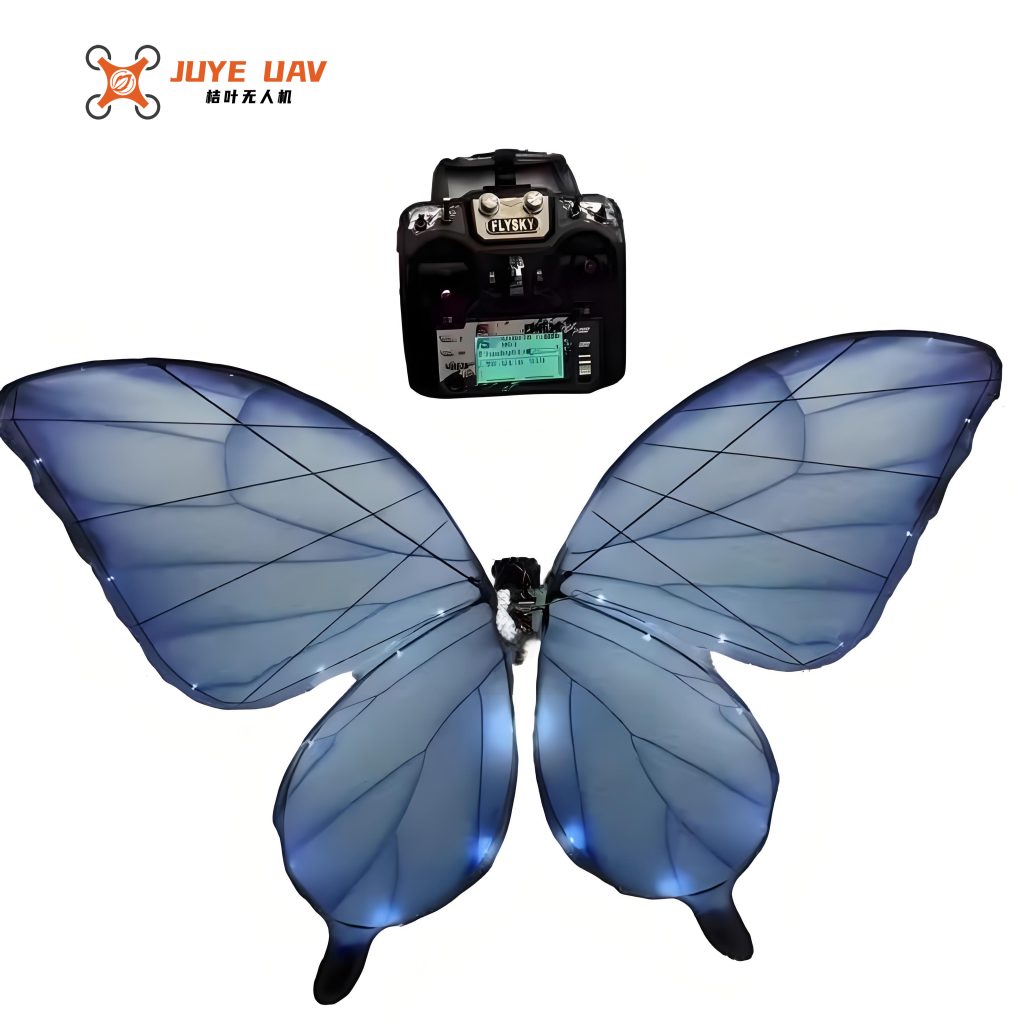
The wings, the most critical components of the bionic butterfly drone, were hand-assembled. Carbon fiber rods were cut and shaped according to the designed venation pattern. The TPU membrane was laser-cut to the precise wing contour. The rods were then bonded to the membrane using a flexible cyanoacrylate adhesive, ensuring a strong yet compliant joint. Finally, the carbon fiber root spar was securely attached to the servo horn, completing the drive assembly. The entire drone was assembled using a combination of press-fits, adhesive bonding, and mechanical fasteners, resulting in a robust yet lightweight structure. The final prototype had a wingspan of 49.8 cm, a body length of 37.9 cm, and a total mass of 32.2 grams, demonstrating the success of the lightweight design philosophy.
Experimental Testing and Performance Analysis
Two key experiments were conducted to evaluate the performance of the bionic butterfly drone prototype: lift force measurement and kinematic analysis of the flapping motion.
1. Lift Force Measurement: A cantilever beam-based test platform was constructed. The drone was mounted such that its lift caused a deflection in a calibrated thin steel beam. A high-precision laser displacement sensor (Keyence LK-G30) measured the beam’s tip deflection in real-time. The beam was first calibrated with known weights to establish a force-displacement relationship with a stiffness $k$ of 569 N/m. The servo was activated to flap the wings, and the displacement data was acquired via a LabVIEW virtual instrument, converted to force, and filtered. The results yielded a time-history of lift generation. The filtered data showed an average lift force of approximately 0.272 N (27.7 grams-force) at a flapping frequency of about 1.1 Hz. While significant, this lift was slightly below the prototype’s weight (0.316 N), indicating the need for further optimization in wing area, flapping frequency, or amplitude to achieve free flight.
2. Wing Kinematics Analysis: To understand the flapping dynamics, a high-speed stereo-vision system was employed. Two high-speed cameras (2900 fps) were positioned orthogonally in front of and to the side of the drone. Markers on the wing spars were tracked in 3D space using motion analysis software. The data provided precise measurements of the flapping angle $\theta(t)$ and the passive twisting angle. The analysis confirmed a flapping frequency of ~1.1 Hz with a maximum flapping amplitude of 136°. The flexible hinge successfully induced a passive twisting motion with an amplitude of about 30°, visually validating the designed phase-lag mechanism between the main wing and forewing during the upstroke.
The control hardware and algorithms were tested in simulation using a real-time data link from the IMU to MATLAB. A 3D model of the drone was rendered and animated based on the live quaternion data from the sensor fusion algorithm, successfully demonstrating the functionality of the attitude estimation pipeline—a prerequisite for stable autonomous flight.
Conclusion and Future Perspectives
This work successfully demonstrated the complete design, manufacturing, and preliminary testing cycle for a novel bionic butterfly drone. The study provided a practical investigation into implementing butterfly-inspired flight mechanics, particularly low-frequency flapping coupled with a passive, flexible wing hinge for enhanced lift generation. The direct servo-drive architecture proved to be a simple and effective solution for actuation, offering direct control over wing kinematics. The prototype, with a wingspan of nearly 50 cm and a mass of 32.2 g, served as a valuable testbed for aerodynamic and kinematic principles.
The experimental results were insightful. The lift measurement confirmed that the current design generates substantial lift, though not yet sufficient for untethered flight under the tested conditions. The kinematic study visually validated the core biomimetic feature: the adaptive, two-stage wing geometry facilitated by the flexible hinge. The development of a custom flight controller with sensor fusion lays the groundwork for future autonomous stabilization.
Future research on this bionic butterfly drone should focus on several key areas to transition from a test prototype to a functional micro aerial vehicle. First, the lift-to-weight ratio must be improved. This could involve optimizing the wing shape and aspect ratio, using even lighter materials for the airframe (e.g., carbon fiber laminates instead of 3D-printed plastic for some parts), selecting a servo with a higher torque-to-weight ratio, or increasing the flapping frequency through a resonant mechanical design. Second, the transition to onboard power is essential. Integrating a lightweight lithium-polymer battery and power regulation circuitry will be a major step toward autonomy, requiring careful weight budget management. Third, the control algorithms need to be refined and tested in free flight. Implementing robust attitude hold and guidance algorithms will enable the bionic butterfly drone to perform controlled maneuvers, ultimately fulfilling its potential for applications in remote sensing and exploration in complex, cluttered environments where conventional drones cannot easily operate.