The evolution of Unmanned Aerial Vehicles (UAVs) has been significantly propelled by the demand for versatile platforms capable of performing complex missions. Among these, Vertical Take-Off and Landing (VTOL) UAVs represent a critical class, blending the hover capability of helicopters with the efficient forward flight of fixed-wing aircraft. The control system for a VTOL UAV, especially during the critical transition phases of take-off, landing, and mode conversion, is paramount to its stability, safety, and operational effectiveness. Traditional control paradigms often fall short in managing the highly nonlinear, underactuated, and dynamically coupled nature of these phases. Therefore, a sophisticated, integrated control strategy is essential. This article delves into the comprehensive design and analysis of control systems for VTOL UAVs, with a particular focus on tilt-rotor configurations, presenting detailed methodologies from mathematical modeling and hardware architecture to advanced control algorithms and software implementation.
The fundamental challenge in controlling a VTOL UAV stems from its hybrid dynamics. A common and highly effective configuration is the quad-tiltrotor, which uses four independently tiltable rotors. This design offers superior control redundancy and agility compared to simpler VTOL designs. The control system’s primary objective is to govern both the vehicle’s attitude (orientation) and its position in three-dimensional space seamlessly across all flight regimes. This requires a hierarchical control structure, typically composed of an inner-loop attitude controller and an outer-loop position/velocity controller. The performance of the entire VTOL UAV hinges on the precise coordination between these loops, robust state estimation, and reliable hardware execution.
1. VTOL UAV Architectures and Control Challenges
Before delving into control system specifics, it is instructive to categorize VTOL UAV types, as their architecture dictates the control approach. The primary configurations include:
| VTOL UAV Type | Description | Key Control Challenges |
|---|---|---|
| Tilt-Rotor (e.g., Quad-Tiltrotor) | Rotors or propellers that can pivot from vertical to horizontal orientation. | Management of transition dynamics, torque coupling during tilt, and actuator saturation. |
| Tilt-Wing | The entire wing, along with its propellers, tilts for transition. | Large shifting of aerodynamic center, complex aerodynamic interference. |
| Tail-Sitter | Airframe sits on its tail for vertical flight and pitches over for horizontal flight. | Extreme attitude changes (90°), control authority at high angles of attack. |
| Lift + Cruise | Separate sets of propellers for vertical lift and forward thrust. | Inefficient due to dead weight, coordination between two propulsion systems. |
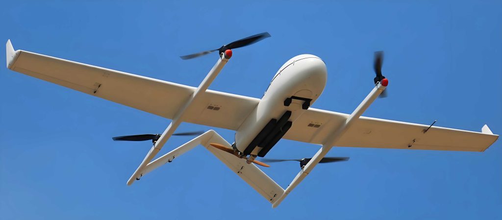
The quad-tiltrotor VTOL UAV is often favored for research and application due to its mechanical simplicity relative to tilt-wing designs and its superior control authority over tail-sitters. Its control model involves four primary control inputs: the thrust magnitudes of each rotor (T1, T2, T3, T4) and their tilt angles (α1, α2, α3, α4). This provides a total of eight actuated degrees of freedom to control six rigid-body degrees of freedom (position x,y,z and attitude φ,θ,ψ), making it an over-actuated system. This over-actuation is beneficial but requires an effective control allocation strategy.
2. Mathematical Modeling of a Tilt-Rotor VTOL UAV
A rigorous dynamic model is the foundation of any robust control system. We define two coordinate frames: the body-fixed frame {B} and the inertial (earth) frame {E}. The vehicle’s state is defined by its position P = [x, y, z]T in {E}, its velocity V = [u, v, w]T in {B}, its attitude represented by Euler angles (Roll φ, Pitch θ, Yaw ψ), and its angular body rates Ω = [p, q, r]T.
2.1 Rigid-Body Dynamics
The translational and rotational dynamics are derived from Newton-Euler equations:
Translational Dynamics:
$$ m \dot{V} + \Omega \times (m V) = F_{total} $$
Where \( m \) is the mass, and \( F_{total} \) is the total force vector acting on the VTOL UAV in {B}, comprising rotor thrusts, gravitational force transformed into {B}, and aerodynamic drag forces \( F_{drag} \).
Rotational Dynamics:
$$ I \dot{\Omega} + \Omega \times (I \Omega) = \tau_{total} $$
Where \( I \) is the inertia tensor, and \( \tau_{total} \) is the total torque vector acting on the body.
2.2 Rotor Force and Torque Generation
For a rotor i with tilt angle αi about the body’s y-axis (for a forward tilt configuration), its thrust vector in {B} is:
$$ F_{rotor,i} = \begin{bmatrix} T_i \sin(\alpha_i) \\ 0 \\ -T_i \cos(\alpha_i) \end{bmatrix} $$
The torque generated by this rotor includes a direct moment due to the thrust vector’s offset from the Center of Gravity (CoG) and a reaction torque due to rotor drag (Qi):
$$ \tau_{rotor,i} = r_i \times F_{rotor,i} + \begin{bmatrix} 0 \\ (-1)^{i+1} Q_i \\ 0 \end{bmatrix} $$
Where \( r_i \) is the position vector of the rotor hub relative to the CoG. The term \( (-1)^{i+1} \) accounts for the direction of rotation (e.g., rotors 1 & 3 clockwise, 2 & 4 counter-clockwise) to balance yaw torque in hover. The total force and torque are the sum of contributions from all four rotors:
$$ F_{total} = \sum_{i=1}^{4} F_{rotor,i} + R^T(\Phi) \begin{bmatrix} 0 \\ 0 \\ mg \end{bmatrix} + F_{drag} $$
$$ \tau_{total} = \sum_{i=1}^{4} \tau_{rotor,i} $$
Where \( R(\Phi) \) is the rotation matrix from {B} to {E} for Euler angles Φ = [φ, θ, ψ]T.
2.3 Simplified Control-Oriented Model for Hover and Low-Speed
For controller design near hover (αi ≈ 0), the model can be linearized. The primary control inputs are often mapped to virtual inputs:
- Total Thrust (U1): Sum of all rotor thrusts. Controls altitude.
- Roll Torque (U2): Differential thrust between left and right rotors.
- Pitch Torque (U3): Differential thrust between front and rear rotors.
- Yaw Torque (U4): Differential reaction torque between clockwise and counter-clockwise rotors.
The tilt angles become active for forward/backward/lateral force generation during transition and forward flight. The linearized attitude dynamics near hover can be approximated as:
$$ I_{xx} \ddot{\phi} = U_2, \quad I_{yy} \ddot{\theta} = U_3, \quad I_{zz} \ddot{\psi} = U_4 $$
And the horizontal position dynamics are coupled through the attitude angles:
$$ \ddot{x} \approx g \theta, \quad \ddot{y} \approx -g \phi $$
This clearly shows the cascaded nature: position is controlled by commanding desired roll and pitch angles.
3. Hierarchical Control System Architecture
The control system for the VTOL UAV employs a hierarchical, nested loop architecture. The following diagram illustrates the data flow and control structure:
| Layer | Function | Typical Update Rate |
|---|---|---|
| Outer Loop: Navigation & Position Control | Accepts waypoints or velocity commands. Computes desired accelerations or directly desired roll/pitch angles and collective thrust. May include trajectory planning. | 50-100 Hz |
| Middle Loop: Velocity Control | (Optional) Takes desired velocity from outer loop and outputs desired attitude and thrust. | 100-200 Hz |
| Inner Loop: Attitude Control | Takes desired roll, pitch, yaw from outer/middle loop and computes required body torques (U2, U3, U4). This is the fastest, most critical loop for stability. | 250-500 Hz |
| Control Allocation | Maps the virtual control inputs (Total Thrust U1, Body Torques U2,U3,U4, and Tilt Commands) to individual rotor thrusts (Ti) and tilt servo commands (αi). | Same as Inner Loop |
| State Estimation | Fuses data from IMU, GPS, Barometer, Magnetometer to provide accurate P, V, Φ, Ω estimates to all control loops. | 200-1000 Hz |
3.1 Attitude Control Design
The inner attitude loop must be highly responsive and robust. A common and effective approach is a Proportional-Integral-Derivative (PID) controller on the angle rates (p, q, r), wrapped within a P or PI controller on the angles (φ, θ, ψ). This is often referred to as a Cascade PID or PI-D controller.
Angle-Level PID: The desired body rates are computed from attitude error.
$$ p_{des} = K_{p,\phi} (\phi_{des} – \phi) + K_{i,\phi} \int (\phi_{des} – \phi) dt $$
$$ q_{des} = K_{p,\theta} (\theta_{des} – \theta) + K_{i,\theta} \int (\theta_{des} – \theta) dt $$
$$ r_{des} = K_{p,\psi} (\psi_{des} – \psi) + K_{i,\psi} \int (\psi_{des} – \psi) dt $$
Rate-Level PID: The virtual torque inputs are computed from body rate error.
$$ U_2 = K_{p,p} (p_{des} – p) + K_{i,p} \int (p_{des} – p) dt + K_{d,p} \dot{p} $$
$$ U_3 = K_{p,q} (q_{des} – q) + K_{i,q} \int (q_{des} – q) dt + K_{d,q} \dot{q} $$
$$ U_4 = K_{p,r} (r_{des} – r) + K_{i,r} \int (r_{des} – r) dt + K_{d,r} \dot{r} $$
For a tilt-rotor VTOL UAV in forward flight, the dynamics change significantly. Gain scheduling or more advanced techniques like Linear Quadratic Regulator (LQR) or Nonlinear Dynamic Inversion (NDI) can be employed. An LQR controller designed for a linearized model around a specific flight condition (e.g., cruise speed) minimizes a cost function J:
$$ J = \int_{0}^{\infty} (x^T Q x + u^T R u) dt $$
where \( x \) is the state error vector and \( u \) is the control input vector. The optimal state-feedback control law is \( u = -K x \), where K is the gain matrix obtained by solving the Algebraic Riccati Equation.
3.2 Position Control Design
The outer loop typically uses PID control. For horizontal position (x,y):
$$ \theta_{des} = K_{p,x} (x_{des} – x) + K_{i,x} \int (x_{des} – x) dt + K_{d,x} (\dot{x}_{des} – \dot{x}) $$
$$ \phi_{des} = -[ K_{p,y} (y_{des} – y) + K_{i,y} \int (y_{des} – y) dt + K_{d,y} (\dot{y}_{des} – \dot{y}) ] $$
The negative sign for φdes ensures correct coupling. For altitude (z) control, the total thrust U1 is computed:
$$ a_{z,des} = K_{p,z} (z_{des} – z) + K_{i,z} \int (z_{des} – z) dt + K_{d,z} (\dot{z}_{des} – \dot{z}) $$
$$ U_1 = \frac{m (g + a_{z,des})}{\cos \phi \cos \theta} $$
The denominator compensates for the loss of vertical thrust component when the VTOL UAV is tilted. For velocity control, the desired acceleration is computed from velocity error and then transformed into tilt/attitude commands.
3.3 Transition Phase Control
The transition phase for a tilt-rotor VTOL UAV, where rotors tilt from α=0° (hover) to α=90° (cruise), is the most complex. A smooth, scheduled transition is critical. One strategy is to define the tilt angle as a function of airspeed or a dedicated transition timer:
$$ \alpha_{cmd}(t) = f(t, V_{air}) $$
During transition, the control allocation must continuously blend the effects of rotor thrust. Before transition, lift is purely from rotor thrust. After transition, lift is primarily aerodynamic, and rotors provide forward thrust. The control system must manage this shifting authority. This often involves scheduling the controller gains (e.g., LQR gains) or using a unified controller like a full-state feedback LQR designed across multiple linearized operating points.
4. Hardware System Design for VTOL UAV Control
The realization of the control algorithms requires a robust and responsive hardware platform. A typical architecture includes:
| Component | Selection & Function | Key Specifications/Interface |
|---|---|---|
| Flight Control Computer (FCC) | Primary processor running navigation, control algorithms, and state estimation. Often a 32-bit ARM Cortex-M4/M7 MCU (e.g., STM32F7, AT32UC3C) or a dedicated flight controller (e.g., Pixhawk). | High clock speed (>150 MHz), FPU, ample SRAM/Flash, multiple timers for PWM generation. |
| Inertial Measurement Unit (IMU) | Core sensor for attitude estimation. Typically a 6-DOF or 9-DOF MEMS module combining 3-axis gyroscope, 3-axis accelerometer, and often a magnetometer. | SPI or I2C interface. Low noise gyros (e.g., <10 mdps/√Hz) and stable accelerometers are critical. |
| Positioning System | GPS module for global position and velocity. Real-Time Kinematic (RTK) GPS can provide centimeter-level accuracy. Barometer for altitude hold. | UART interface (NMEA/UBX protocols). Update rate ≥5 Hz, higher for aggressive control. |
| Remote Control (RC) Receiver | Receives manual pilot commands. 2.4GHz systems like Futaba, FrSky. Used for manual override, mode switching, and failsafe. | PPM or SBUS signal output. Connected to FCC via a dedicated input pin or UART. |
| Telemetry Radio | Bi-directional data link for ground station communication. Transmits telemetry (state, logs) and receives commands. | UART interface to FCC. Common frequencies: 433 MHz, 915 MHz, 2.4 GHz. |
| Electronic Speed Controllers (ESCs) | Drive brushless DC motors for rotors. Interpret PWM or digital (DShot, OneShot) signals from FCC. | PWM input (50-500Hz). High current rating matching motors. |
| Servo Controllers | Drive the tilt servos for rotors. Can be standard RC servos or smart serial servos. | PWM input or digital bus (UART). |
| Power Management | Distributes power from the main battery (e.g., 4S LiPo) to all components, providing stable 5V/3.3V rails. | High-efficiency switching regulators, current sensors for battery monitoring. |
5. Software Implementation and Data Flow
The software architecture is typically built around a real-time operating system (RTOS) or a super-loop with precisely timed interrupts to ensure deterministic execution of critical tasks.
5.1 State Estimation Sensor Fusion
Raw sensor data is noisy and biased. A sensor fusion algorithm, most commonly a Complementary Filter or an Extended Kalman Filter (EKF), is used to obtain accurate state estimates.
Complementary Filter for Attitude: A simple yet effective method blending high-frequency gyro data with low-frequency accelerometer/magnetometer data.
$$ \hat{\theta} = \alpha (\hat{\theta}_{prev} + g_y \cdot dt) + (1-\alpha) \theta_{acc} $$
where \( \theta_{acc} = \arctan2(a_y, a_z) \), and α is a tuning parameter close to 1 (e.g., 0.98).
Extended Kalman Filter (EKF): The industry standard for high-performance VTOL UAVs. It uses a nonlinear process model (the dynamics from Section 2) and linearizes it around the current estimate. It predicts the state based on the model and then corrects it using sensor measurements (IMU, GPS, baro). The EKF provides optimal estimates of position, velocity, attitude, and even sensor biases. The prediction and update steps are defined by:
Prediction:
$$ \hat{x}_{k|k-1} = f(\hat{x}_{k-1|k-1}, u_{k-1}) $$
$$ P_{k|k-1} = F_k P_{k-1|k-1} F_k^T + Q_k $$
Update:
$$ y_k = z_k – h(\hat{x}_{k|k-1}) $$
$$ S_k = H_k P_{k|k-1} H_k^T + R_k $$
$$ K_k = P_{k|k-1} H_k^T S_k^{-1} $$
$$ \hat{x}_{k|k} = \hat{x}_{k|k-1} + K_k y_k $$
$$ P_{k|k} = (I – K_k H_k) P_{k|k-1} $$
Where \( F_k \) is the Jacobian of \( f \) w.r.t. the state, and \( H_k \) is the Jacobian of \( h \) w.r.t. the state.
5.2 Communication Protocols and Data Handling
Robust intra- and inter-system communication is vital.
- I2C/SPI: Used for communication between the FCC and onboard sensors (IMU, magnetometer, airspeed sensor).
- UART: Used for communication with GPS, telemetry radio, and sometimes the RC receiver (SBUS).
- PWM/PPM: Traditional signals for ESCs and servos. Modern digital protocols (DShot, UAVCAN) are gaining popularity for higher reliability and bandwidth.
- MAVLink: A highly efficient, widely adopted micro air vehicle communication protocol used over the telemetry link. It standardizes the message set for commanding the VTOL UAV and receiving telemetry.
Data from the RC receiver, typically a PPM sum signal or serial bus (SBUS), is decoded to extract channel values for throttle, roll, pitch, yaw, and mode switches. This is done in a high-priority interrupt. The control loops run in a timed task, reading the current state estimate and RC commands, computing control outputs, and executing the control allocation to generate PWM/digital signals for the actuators.
5.3 Control Allocation for Tilt-Rotor VTOL UAV
This module solves for individual rotor thrusts Ti and tilt angles αi given the virtual commands (U1, U2, U3, U4) and potentially direct force commands in forward flight. For a standard quadcopter (no tilt), this is a simple linear mapping. For a tilt-rotor, it becomes an optimization problem because the system is over-actuated. A common practical approach is to use a prioritized mixing strategy:
- Use differential thrust for roll and pitch torques (U2, U3).
- Use differential rotor speed for yaw torque (U4).
- Command all rotors to tilt uniformly to achieve a desired forward/lateral force component, calculated from the outer-loop’s velocity error. The total thrust U1 is then adjusted to maintain altitude as the vertical component of rotor thrust decreases with tilt.
This can be formulated as a constrained optimization problem to also respect actuator limits (min/max thrust, tilt angle, tilt rate):
$$ \min_{T_i, \alpha_i} \| \Gamma(T_i, \alpha_i) – U_{des} \| $$
$$ \text{subject to: } T_{min} \le T_i \le T_{max}, \quad \alpha_{min} \le \alpha_i \le \alpha_{max} $$
Where \( \Gamma \) is the function mapping rotor commands to virtual controls.
6. Simulation, Testing, and Tuning
Developing a control system for a VTOL UAV necessitates rigorous simulation before flight testing. Tools like MATLAB/Simulink, Gazebo with ROS, or jMAVSim are invaluable. A high-fidelity simulation includes:
- The nonlinear dynamic model from Section 2.
- Models of sensor noise and delays.
- Models of actuator dynamics and limits.
- Wind and disturbance models.
- The complete control and estimation algorithms.
Controller gains are initially tuned in simulation. Methods like manual tuning, Ziegler-Nichols, or automated optimization (e.g., using Simulink’s Response Optimizer) can be applied. The transition logic and control allocation are thoroughly validated in simulation across the entire flight envelope.
Flight testing follows a structured, safety-oriented procedure: (1) Hardware-in-the-Loop (HIL) testing where the real FCC runs code against a simulated plant. (2) Tethered hover tests for basic attitude and altitude control. (3) Free-flight hover and low-speed maneuvering. (4) Gradual transition flight tests, initially at higher altitude. Data logging is crucial for post-flight analysis and fine-tuning.
7. Conclusion and Future Directions
The design of a control system for a VTOL UAV, particularly a tilt-rotor configuration, is a multifaceted engineering challenge integrating dynamics, control theory, electronics, and software. A successful system relies on a well-derived dynamic model, a hierarchical control architecture with robust inner-loop attitude stabilization, sophisticated sensor fusion for state estimation, and a reliable hardware/software co-design. The transition phase demands special attention through gain scheduling or advanced multi-model control strategies.
Future advancements in VTOL UAV control are likely to focus on:
- Increased Autonomy: Integration of path planning, obstacle avoidance, and vision-based navigation for complex environments.
- Adaptive & Learning-Based Control: Use of Model Reference Adaptive Control (MRAC) or Reinforcement Learning (RL) to handle model uncertainties and changing conditions (e.g., payload, damage) in real-time.
- Fault-Tolerant Control (FTC): Advanced algorithms to detect actuator or sensor failures and reconfigure control allocation to maintain stable flight, exploiting the inherent redundancy in a multi-rotor VTOL UAV.
- Swarm Coordination: Development of control laws for fleets of VTOL UAVs operating collaboratively.
As these technologies mature, the operational scope and reliability of VTOL UAVs will expand dramatically, cementing their role in applications from logistics and inspection to advanced air mobility. The continuous refinement of their control systems remains the cornerstone of this progress.