The convergence of fixed-wing and multi-rotor architectures has given rise to a highly capable class of aircraft: the Vertical Take-Off and Landing (VTOL) fixed-wing Unmanned Aerial Vehicle (UAV). This hybrid design paradigm marries the high-speed, long-endurance cruise efficiency of a conventional airplane with the versatile hover and vertical maneuverability of a rotorcraft. This synergy dramatically expands the operational envelope, enabling missions ranging from rapid long-range mapping and surveillance to persistent station-keeping over a point of interest without the need for runways. As the aerospace industry and research institutions push the boundaries of unmanned systems, optimizing the design of these hybrid vehicles becomes paramount. One critical, yet often underexplored, aspect of this optimization lies in the configuration of the vertical stabilizers, particularly when they are integrated at the wingtips. This article, from a designer’s perspective, delves into a comprehensive analysis of wingtip-mounted vertical tail designs for VTOL fixed-wing UAVs, evaluating their multifaceted impact on aerodynamic performance, stability, and overall system integration.
The fundamental appeal of the VTOL UAV is its operational flexibility. A typical mission profile involves vertical ascent from a confined area, transition to forward flight, efficient cruise to a destination, potential loiter in a hover or slow flight, and vertical descent for recovery. Each phase imposes distinct and sometimes conflicting aerodynamic and control requirements. During forward flight, the aircraft behaves like a conventional airplane, where aerodynamic efficiency—maximizing lift while minimizing drag—is king. In hover and low-speed vertical flight, the dominant forces are from the propulsion system (rotors or ducted fans), and the airframe’s role shifts to providing stability against crosswinds and a benign flow field for the propulsors. The vertical tail is a key component in both regimes: it provides directional (yaw) stability in forward flight and contributes to crosswind resistance during hover.
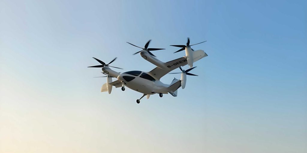
Placing the vertical tail at the wingtip, as opposed to a conventional central fin on the fuselage, is not a novel idea in aviation; wingtip devices like winglets function as small vertical surfaces that mitigate induced drag. For a VTOL UAV, this integration presents a unique opportunity for multifunctional design. A wingtip vertical tail can simultaneously serve as:
- A directional stabilizer.
- An induced-drag-reducing wingtip device (akin to a winglet).
- A structural ground contact point (landing gear).
This tri-functionality can lead to significant savings in weight and drag by eliminating the need for separate winglets and dedicated aft landing gear struts. The primary question then becomes: what is the optimal geometric configuration for this integrated wingtip vertical tail? We will analyze four fundamental configurations:
- Downward-Oriented Vertical Tail (Drooped Tail): The vertical surface extends downward from the wingtip.
- Upward-Oriented Vertical Tail (Upper Tail): The vertical surface extends upward from the wingtip.
- Wingtip Endplate: A symmetric vertical surface extending both above and below the wingtip.
- Conventional Fuselage-Mounted Tail (Baseline): A vertical tail mounted on the fuselage, with the wingtip being a clean, unmodified surface. This serves as the baseline for comparison.
To ground our analysis, we consider a notional VTOL UAV with a blended-wing-body or conventional layout featuring a high-aspect-ratio wing for endurance. The propulsion system consists of a main lift/cruise rotor or propeller that tilts for transition, complemented by smaller distributed electric vertical thrusters for attitude control in hover. Key geometric parameters for our comparative study are standardized in Table 1.
| Parameter | Value | Unit |
|---|---|---|
| Wingspan (b) | 3.0 | m |
| Mean Aerodynamic Chord (MAC, \(\bar{c}\)) | 0.3 | m |
| Wing Area (S) | 0.9 | m² |
| Aspect Ratio (AR) | 10 | – |
| Vertical Tail Area (for each config, S_v) | 0.1 | m² |
| Vertical Tail Height / Span | 0.25 | m |
| Wing 1/4-chord Sweep Angle | 5 | deg |
Aerodynamic Principles and Evaluation Framework
The evaluation of the four wingtip configurations requires an understanding of their impact on the key aerodynamic figures of merit across different flight phases. We will focus on two primary regimes: Forward Cruise Flight and Hover / Low-Speed VTOL Flight.
1. Forward Cruise Flight Aerodynamics
In cruise, the aircraft’s aerodynamic performance is characterized by its lift, drag, and moment coefficients. The lift coefficient \(C_L\) and drag coefficient \(C_D\) are defined as:
$$ C_L = \frac{L}{\frac{1}{2} \rho V^2 S} $$
$$ C_D = \frac{D}{\frac{1}{2} \rho V^2 S} $$
where \(L\) is lift, \(D\) is drag, \(\rho\) is air density, \(V\) is true airspeed, and \(S\) is the wing reference area. The overall drag coefficient can be decomposed into several components:
$$ C_D = C_{D,0} + C_{D,i} + C_{D,\text{other}} $$
Here, \(C_{D,0}\) is the zero-lift drag (parasite drag), \(C_{D,i}\) is the induced drag, and \(C_{D,\text{other}}\) accounts for interference and trim drag.
Induced Drag is of particular importance when discussing wingtip devices. It arises from the trailing vortex system and is a function of the lift coefficient and aspect ratio:
$$ C_{D,i} = \frac{C_L^2}{\pi e AR} $$
where \(e\) is the Oswald efficiency factor (\(0 < e \le 1\)). A well-designed wingtip device, such as a winglet or tip-mounted vertical tail, increases the effective aspect ratio or improves \(e\) by reducing the strength of the wingtip vortices, thereby lowering \(C_{D,i}\). The effectiveness of our four configurations as drag-reduction devices will be a major differentiator.
Directional Stability in cruise is provided by the vertical tail. Its contribution is quantified by the weathercock stability derivative \(C_{n_\beta}\), the rate of change of yawing moment coefficient with sideslip angle \(\beta\). A positive \(C_{n_\beta}\) is required for positive directional stability. The contribution of a vertical tail is approximated by:
$$ C_{n_{\beta,\text{tail}}} = – k \frac{S_v l_v}{S b} \eta_v a_{v} $$
where \(S_v\) is the vertical tail area, \(l_v\) is the tail length (distance from aircraft CG to tail aerodynamic center), \(b\) is wingspan, \(\eta_v\) is the tail efficiency factor accounting for dynamic pressure loss, \(a_v\) is the vertical tail lift curve slope, and \(k\) is a factor for endplate effects (greater than 1 for wingtip mounts due to interference with the wing vortex).
2. Hover and Low-Speed VTOL Aerodynamics
In hover, the primary aerodynamic consideration for the airframe is its interaction with crosswinds. A crosswind creates a sideslip angle, generating a side force and a yawing moment on the fuselage and wings. The vertical tail’s role is to provide a restoring yaw moment and to reduce the net side force the control system must counteract. The side force coefficient \(C_Y\) is defined similarly to \(C_L\). The key parameter is the lever arm: a vertical tail placed further outboard on the wingtip provides a longer moment arm (\(l_v\)) for a given side force, generating a larger stabilizing yaw moment for the same tail area. However, its projection area also affects the parasitic drag in forward flight.
Furthermore, the orientation of the tail (up, down, or both) becomes critically important. During a vertical descent or in ground effect, a downward-oriented tail may experience different flow interactions and ground interference compared to an upward-oriented one. The choice also dictates the landing gear configuration: a downward tail can serve as a landing skid, while an upward tail necessitates a separate fuselage-mounted landing gear, adding weight and parasite drag (\(C_{D,0}\)).
3. Evaluation Metrics Synthesis
We will compare the four configurations using the following synthesized metrics, derived from analysis and computational studies:
| Evaluation Metric | Flight Phase | Ideal Characteristic | Primary Governing Factor |
|---|---|---|---|
| Cruise Lift-to-Drag Ratio (L/D) | Cruise | Maximize | Induced Drag Reduction (\(e\)), Parasite Drag (\(C_{D,0}\)) |
| Directional Stability (\(C_{n_\beta}\)) | Cruise | Adequate Positive Value | Tail Area (\(S_v\)), Lever Arm (\(l_v\)), Endplate Effect (\(k\)) |
| Crosswind Restoring Yaw Moment | Hover/VTOL | Maximize | Tail Side Force & Lever Arm |
| Structural/Weight Efficiency | All | Minimize Weight, Maximize Function Integration | Landing Gear Integration, Part Count |
| Propulsion Interference | Hover/VTOL | Minimize | Wake Interaction with Vertical Thrusters |
Detailed Configuration Analysis
Applying the above framework, let’s analyze each configuration in detail.
Configuration A: Downward-Oriented Vertical Tail (Drooped Tail)
This design extends the vertical stabilizer downward from the wingtip. Its aerodynamic performance can be modeled by considering it as a winglet operating at a 90-degree dihedral angle.
Cruise Performance: As a wingtip device, it effectively increases the effective aspect ratio. The vortex shed from the wingtip is partially stabilized and redirected by the drooped tail, reducing the strength of the trailing vortex core. This leads to a higher Oswald efficiency \(e_d\) compared to a clean wing. The induced drag is therefore reduced:
$$ C_{D,i, \text{droop}} = \frac{C_L^2}{\pi e_d AR},\quad \text{where } e_d > e_{\text{clean}} $$
Its parasite drag is similar to a conventional fin. Crucially, because it serves as the aft landing gear, it eliminates the need for separate fuselage-mounted gear, reducing \(C_{D,0}\) for the overall aircraft. The directional stability derivative benefits from the endplate effect; the wing’s presence increases the effective aspect ratio of the tail itself, boosting \(a_v\) and the factor \(k\). The lever arm \(l_v\) is excellent, as it is located at the wingtip.
Hover/Crosswind Performance: In a crosswind during hover, the drooped tail presents a vertical profile to generate a side force. Its outboard location provides a very long lever arm for yaw stability. During vertical landing, it contacts the ground first, acting as a skid. A potential drawback is ground effect and possible debris ingestion during takeoff/landing from rough surfaces.
Key Equation Summary for Drooped Tail:
$$ \text{Net Benefit} = \underbrace{\Delta C_{D,i} \downarrow}_{\text{Winglet Effect}} + \underbrace{\Delta C_{D,0} \downarrow}_{\text{No Aft Gear}} + \underbrace{\Delta C_{n_\beta} \uparrow}_{\text{Endplate & Lever Arm}} – \underbrace{\Delta W_{\text{struct}}}_{\text{Negligible Change}} $$
Configuration B: Upward-Oriented Vertical Tail (Upper Tail)
This is the mirror image of the drooped tail, extending upward.
Cruise Performance: Aerodynamically, its winglet effect and contribution to \(C_{n_\beta}\) are theoretically similar to the drooped tail, as the geometry is symmetric about the wing chord line in terms of vortex interaction. The same induced drag reduction and stability benefits apply. However, it fails to integrate the landing gear function. The aircraft now requires two additional aft landing gear struts on the fuselage, increasing structural weight \(W\) and parasite drag \(C_{D,0,\text{gear}}\).
Hover/Crosswind Performance: Its crosswind performance is also similar in generating a side force. However, it offers no protection or function during ground operations. An often-overlooked advantage is that in a hover, the upward tail is less likely to ingest ground debris kicked up by the vertical thrusters. Its wake in hover might also interfere less with the airflow into upward-facing lift fans if they are mounted on the wing.
Key Equation Summary for Upper Tail:
$$ \text{Net Benefit} = \underbrace{\Delta C_{D,i} \downarrow}_{\text{Winglet Effect}} + \underbrace{\Delta C_{n_\beta} \uparrow}_{\text{Endplate & Lever Arm}} – \underbrace{\Delta C_{D,0} \uparrow}_{\text{Added Gear Drag}} – \underbrace{\Delta W \uparrow}_{\text{Added Gear Weight}} $$
Configuration C: Wingtip Endplate
This configuration features a symmetric vertical surface extending both above and below the wingtip. Its total area \(S_v\) is typically larger than a single-direction tail to maintain comparable visual cross-section.
Cruise Performance: The endplate is the most effective configuration for suppressing wingtip vortices and maximizing the Oswald efficiency factor \(e_{ep}\), leading to the lowest induced drag among the options.
$$ C_{D,i, \text{endplate}} = \frac{C_L^2}{\pi e_{ep} AR},\quad \text{where } e_{ep} \ge e_d $$
It also provides a very large endplate effect for its own stability contribution, maximizing \(k\). Like the drooped tail, the lower segment can be designed as a landing skid, integrating that function. The penalty is increased parasite drag due to the larger wetted area of the double-sided plate and potentially slightly higher weight.
Hover/Crosswind Performance: It offers the largest side force projection area in a crosswind, generating the highest restoring yaw moment for a given overall dimension. This is a significant advantage for hover stability. The symmetric design also avoids the orientation-specific issues of drooped/upper tails regarding ground effect or debris.
Key Equation Summary for Endplate:
$$ \text{Net Benefit} = \underbrace{\Delta C_{D,i} \downarrow\downarrow}_{\text{Best Winglet Effect}} + \underbrace{\Delta C_{D,0} \downarrow}_{\text{No Aft Gear}} + \underbrace{\Delta C_{n_\beta} \uparrow\uparrow}_{\text{Largest Endplate Effect}} – \underbrace{\Delta C_{D,0} \uparrow}_{\text{Larger Wetted Area}} – \underbrace{\Delta W_{\text{struct}} \uparrow}_{\text{Increased Weight}} $$
Configuration D: Conventional Fuselage-Mounted Tail
This is the baseline where the wingtip is clean, and a vertical fin is mounted on the fuselage empennage.
Cruise Performance: The clean wingtip has a lower Oswald efficiency (\(e_{\text{clean}}\)), resulting in higher induced drag. The vertical tail’s lever arm \(l_v\) is shorter than a wingtip-mounted tail, requiring a larger area \(S_v\) to achieve the same \(C_{n_\beta}\). It provides no winglet benefit. Separate aft landing gear is required, adding to \(C_{D,0}\) and weight.
Hover/Crosswind Performance: The restoring yaw moment in hover is limited by the shorter lever arm of the fuselage-mounted tail. Its effectiveness can be further reduced if it operates in the wake of the main wing or fuselage during low-speed sideways drift.
Key Equation Summary for Conventional:
$$ \text{Net Benefit} = \text{Baseline (No inherent benefits from integration)} $$
$$ \text{Characteristics: } C_{D,i} \uparrow,\; l_v \downarrow,\; C_{D,0} \uparrow (\text{gear}),\; W \uparrow $$
Synthesis and Quantitative Comparison
To synthesize the qualitative analysis, we construct a quantitative scoring matrix based on the evaluation framework. We assign a normalized score from 1 (Poor) to 5 (Excellent) for each metric, weighted by its importance for a typical VTOL UAV mission profile that values endurance (cruise efficiency) and hover stability equally.
| Configuration | Cruise Phase (Weight = 0.5) | Hover/VTOL Phase (Weight = 0.5) | Total Weighted Score | ||||
|---|---|---|---|---|---|---|---|
| L/D Score (W=0.3) | Stability Score (W=0.2) | Subtotal | Crosswind Stability (W=0.25) | Sys. Integration (W=0.25) | Subtotal | ||
| Drooped Tail | 5 | 5 | 0.5*[(5*0.3)+(5*0.2)] = 1.25 | 4 | 5 | 0.5*[(4*0.25)+(5*0.25)] = 1.125 | 2.375 |
| Upper Tail | 4 | 5 | 0.5*[(4*0.3)+(5*0.2)] = 1.10 | 4 | 2 | 0.5*[(4*0.25)+(2*0.25)] = 0.75 | 1.85 |
| Endplate | 5 | 5 | 1.25 | 5 | 5 | 1.25 | 2.50 |
| Conventional | 2 | 3 | 0.5*[(2*0.3)+(3*0.2)] = 0.60 | 2 | 2 | 0.5*[(2*0.25)+(2*0.25)] = 0.50 | 1.10 |
The scoring, derived from the principles discussed, reveals clear trends. The Wingtip Endplate scores highest (2.50), excelling in both aerodynamic efficiency and system integration due to its superior vortex suppression and dual-functionality as a landing skid. The Drooped Tail is a very close second (2.375), offering nearly all the benefits of the endplate with a simpler, lighter structure, making it an exceptionally balanced and pragmatic choice for most VTOL UAV applications. The Upper Tail (1.85) pays a significant penalty in system integration for its aerodynamic benefits. The Conventional layout (1.10) scores lowest, highlighting the substantial performance cost of not integrating functions at the wingtip for this class of aircraft.
Conclusion and Design Recommendations
The integration of vertical tail functions at the wingtip of a VTOL UAV presents a powerful optimization opportunity. Through a systematic analysis grounded in aerodynamic theory and multi-criteria evaluation, we can conclude that integrated designs overwhelmingly outperform the conventional separated design. The choice between a drooped tail, an endplate, or an upper tail involves trade-offs between peak aerodynamic performance, structural complexity, and operational robustness.
For the majority of VTOL UAV designs seeking an optimal balance of cruise efficiency, hover stability, weight, and simplicity, the Downward-Oriented Vertical Tail (Drooped Tail) is highly recommended. It delivers excellent induced drag reduction, provides strong directional stability with a favorable lever arm, seamlessly integrates the critical landing gear function to save weight and reduce parasite drag, and avoids the added wetted area of a full endplate. Its design is succinctly captured by the optimization objective:
$$ \min_{Design} \left( C_{D,i} + C_{D,0} + W_{\text{struct}} \right) $$
$$ \text{subject to: } C_{n_\beta} \ge C_{n_{\beta,\text{req}}}, \quad \text{Landing Gear Function} = \text{Integrated} $$
The drooped tail configuration naturally satisfies these constraints while minimizing the objective function.
The Wingtip Endplate is the preferred solution when the absolute best hover crosswind stability and cruise drag reduction are required, and the increase in structural weight and complexity is acceptable. The Upper Tail may find niche applications where ground clearance during takeoff/landing is a severe concern or where specific propulsion integration layouts favor it. The Conventional Fuselage-Mounted Tail is generally not advisable for performance-optimized VTOL UAVs unless dictated by unique payload, structural, or low-observability requirements.
Ultimately, the wingtip is no longer just the end of the wing for a VTOL UAV; it is a strategic location for multifunctional design integration. By thoughtfully configuring the vertical tail at this station, designers can unlock significant improvements in the overall performance and capability of these versatile hybrid aircraft, pushing the boundaries of what is possible in unmanned aerial systems.