The evolution of unmanned aerial systems continuously demands platforms that reconcile operational flexibility with mission endurance. In this context, Vertical Take-Off and Landing (VTOL) fixed-wing Unmanned Aerial Vehicles (UAVs) have emerged as a pivotal solution, merging the hover capability and low-speed agility of rotary-wing systems with the high-speed cruise efficiency and extended range of fixed-wing aircraft. Among the various VTOL configurations, the tail-sitter architecture presents a conceptually elegant and structurally efficient approach. This article, from our engineering perspective, delves into the design, modeling, control, and flight testing of a novel 10 kg-class, electrically powered, canard-configured tail-sitter VTOL UAV system. We aim to provide a detailed technical exposition that addresses the inherent challenges of this configuration, particularly the critical transition phases, while highlighting the advantages it holds over more common compound helicopter or multirotor-fixed-wing hybrid (often termed ‘quadplane’) designs.
The quadplane configuration, which simply mounts a multirotor system atop a conventional fixed-wing airframe, has gained popularity due to its straightforward mechanical integration and relatively simple control segmentation. However, it introduces significant penalties: the added weight of the redundant multirotor motors and propellers during cruise constitutes parasitic mass, and the exposed multirotor structure increases aerodynamic drag. These factors directly undermine the platform’s primary advantage—extended endurance. Our research initiative sought to overcome these limitations by revisiting the pure tail-sitter concept but augmenting it with a distributed electric propulsion system inspired by multirotor reliability. The resulting VTOL UAV embodies a synthesis where the entire airframe rotates to transition between flight regimes, eliminating dedicated hover propulsion units and their associated drag, while leveraging multiple motors for enhanced control authority and redundancy.
The selection of a canard layout is a critical aerodynamic innovation in our VTOL UAV design. For small-scale UAVs, achieving a high lift-to-drag ratio is paramount for endurance. The canard foreplane contributes positive lift, unlike a conventional tailplane which typically generates negative lift for stability. This synergistic lifting effect increases the overall maximum lift coefficient and improves the lift-to-drag ratio. Furthermore, the canard provides powerful pitch control moments, which are essential during the aggressive pitch maneuvers of the VTOL transition phases. This allows for a reduction in the control authority required from the main wing elevons, reserving their deflection range for robust roll control and gust rejection during cruise. The integrated design philosophy focuses on optimizing the entire system—aerodynamics, propulsion, flight control, and mission management—to realize a practical and high-performance VTOL UAV solution.
System Architecture and Platform Design of the VTOL UAV
The development of our VTOL UAV began with defining key performance parameters suitable for tactical, portable operations. The target was a gross take-off weight of approximately 10 kg, leveraging electric propulsion for simplicity, low acoustic signature, and ease of maintenance. The primary design drivers were vertical take-off/landing capability, a target cruise speed of 20-25 m/s, an operational altitude up to 2500 m, and maximizing endurance within the weight and volume constraints of a man-portable system.
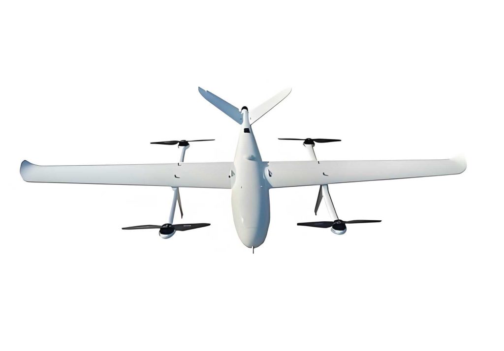
The aerodynamic configuration is a twin-boom, canard-layout flying wing. The airframe is primarily constructed from composite materials (carbon fiber and glass fiber reinforced polymers) to achieve an optimal strength-to-weight ratio. The canard surface is equipped with an elevator, while the main wing features elevons for combined pitch and roll control in fixed-wing mode. Four brushless electric motors are strategically mounted: two on the canard tips and two on the wingtips. All four propellers are in a tractor configuration. For hover (tail-sitter mode), the aircraft rests on its tail booms, with the nose pointing vertically upward. In this attitude, the four motors operate as a standard quadcopter, with differential thrust managing pitch, roll, yaw, and collective thrust managing altitude.
The key parameters of the VTOL UAV platform are summarized below:
| Parameter | Value | Description |
|---|---|---|
| Gross Take-Off Weight | 10.5 kg | Including payload and batteries |
| Wingspan | 2.4 m | Total span from wingtip to wingtip |
| Wing Reference Area | 0.7 m² | Projected area of the main wing |
| Aspect Ratio | ~8.2 | Optimized for cruise efficiency |
| Motor Quantity & Type | 4 x Brushless | High KV, maximum thrust ~50 N each |
| Propeller Diameter | 12 inches | Optimized for both hover and cruise |
| Battery | Li-Polymer, 6S | Capacity tailored for mission profile |
| Cruise Speed | 20-25 m/s | Target efficient flight speed |
| Stall Speed (Fixed-Wing) | ~14 m/s | Defines low-speed transition boundary |
The flight control system (FCS) is the central nervous system of any VTOL UAV, and for this complex platform, a robust, adaptive, and redundant system is non-negotiable. We employed a modular, industry-grade autopilot system. Its core components include a main flight control computer (FCC) based on a high-performance STM32 microcontroller running a real-time operating system (RTOS), a dual-redundant Inertial Measurement Unit (IMU) cluster with MEMS gyros, accelerometers, and barometers, a combined GPS/Magnetometer module, and a secure digital data link for telemetry and command. The FCC executes all guidance, navigation, and control (GNC) algorithms, manages flight mode transitions, and logs extensive flight data. The software architecture supports model-based design, allowing for control law development and validation in simulation environments like MATLAB/Simulink before direct deployment to the hardware.
Flight Regimes and Hierarchical Control Strategy
The operational envelope of this tail-sitter VTOL UAV encompasses five distinct flight phases, each with unique dynamics and control requirements: 1) Vertical Take-off & Hover, 2) Transition from Hover to Cruise (Nose-Over), 3) Fixed-Wing Cruise, 4) Transition from Cruise to Hover (Pull-Up), and 5) Vertical Landing. A seamless and safe transition between rotary-dominated and fixed-wing-dominated flight is the principal challenge.
We adopted a hierarchical, mode-dependent control architecture. The inner loops always stabilize attitude (pitch, roll, yaw), while outer loops manage velocity, position, and flight path. The key innovation lies in the controller blending and mode switching logic during transitions.
Multirotor (Hover) Mode Control
When the VTOL UAV is in a vertical attitude (angles near ±90° pitch), it is controlled as a standard quadcopter. The four motors (Front-Left, Front-Right, Rear-Left, Rear-Right) are mapped to body-axis torques and collective thrust. A modified Proportional-Integral-Derivative (PID) control structure provides robust stabilization. The attitude control loop takes desired attitude angles ($\phi_{des}, \theta_{des}, \psi_{des}$) and generates required body-axis torque commands ($\tau_{\phi}, \tau_{\theta}, \tau_{\psi}$). For a standard ‘X’ quadcopter configuration with motors generating forces $F_1$ to $F_4$, the mapping is:
$$
\begin{aligned}
F_{total} &= F_1 + F_2 + F_3 + F_4 \\
\tau_{\phi} &= L \cdot (F_2 + F_3 – F_1 – F_4) / \sqrt{2} \\
\tau_{\theta} &= L \cdot (F_1 + F_2 – F_3 – F_4) / \sqrt{2} \\
\tau_{\psi} &= C \cdot (F_1 + F_3 – F_2 – F_4)
\end{aligned}
$$
where $L$ is the arm length from center of gravity to motor, and $C$ is a coefficient relating thrust to reactive torque. The outer loop typically consists of a velocity or position controller that outputs desired tilt angles to the inner loop.
Fixed-Wing Mode Control
In level flight, the VTOL UAV behaves as a conventional fixed-wing aircraft. Only the two wing motors are used for primary propulsion, while the canard motors are idled (providing potential for differential thrust yaw control if needed). Control surfaces (canard elevator and wing elevons) become the primary effectors. A classical cascade control structure is used: a roll attitude hold loop for coordinated turns, a pitch attitude hold loop for climb/descent, and a heading or course hold loop for navigation. Airspeed is maintained via throttle control on the wing motors. The longitudinal control law for pitch, for instance, can be structured as:
$$
\delta_e = K_{\theta} (\theta_{des} – \theta) + K_q \cdot q + K_{V} (V_{des} – V) + \text{Integral Term}
$$
where $\delta_e$ is the canard elevator deflection, $\theta$ is pitch angle, $q$ is pitch rate, $V$ is airspeed, and $K$’s are control gains.
The Critical Transition Control Logic
The transition phases are the most dynamic and sensitive part of the VTOL UAV’s flight. A carefully designed state machine governs the blending of multirotor and fixed-wing control laws and the management of motor assignments.
a) Hover-to-Cruise (Nose-Over) Transition:
1. Initiation: From a stable hover at a safe altitude, the VTOL UAV receives the transition command.
2. Pitch-Over Acceleration: The multirotor controller is given a large negative pitch angle command (e.g., -40° relative to the world horizontal). This causes the aircraft to nose forward. All four motors provide thrust, primarily vectored to counteract gravity and provide forward acceleration. Airspeed builds rapidly.
3. Blended Control Phase: When airspeed exceeds a pre-defined threshold (e.g., >15 m/s, safely above stall speed), the control system enters a blended mode. The desired attitude trajectory is now a smooth function from the current nose-down angle back to level flight (0°). The control allocator dynamically mixes inputs: the multirotor control laws still generate torque demands based on attitude error, but these are now met by a combination of differential motor thrust and control surface deflections. The fixed-wing controller begins to actively contribute as aerodynamic forces become significant.
4. Completion: Once the VTOL UAV achieves a steady level flight attitude and airspeed exceeds the cruise speed, the multirotor control laws are completely phased out. The canard motors are shut down, and the aircraft operates purely in fixed-wing mode. The transition logic is formalized as a function of airspeed $V$:
$$
\text{Control Effort} = \alpha(V) \cdot \text{Multirotor Law} + (1-\alpha(V)) \cdot \text{Fixed-Wing Law}
$$
where $\alpha(V)$ is a monotonic decreasing function from 1 to 0 over a defined airspeed range $[V_{start}, V_{end}]$.
b) Cruise-to-Hover (Pull-Up) Transition:
1. Setup: The VTOL UAV returns to a predefined transition zone and reduces airspeed to a safe but efficient value.
2. Aggressive Pull-Up: A large positive pitch angle command (e.g., +85°) is issued. Initially, this is handled by the fixed-wing control surfaces pulling the nose up. Simultaneously, all four motors are spooled up to maximum thrust to arrest the decay in airspeed and provide lift as the wing loses effectiveness at high angles of attack.
3. Blended Stabilization: As the aircraft pitches past 45°, the multirotor control laws are ramped up to full authority to stabilize the increasingly unstable pendulum-like dynamics. The control surfaces remain active but their effectiveness diminishes as airflow becomes partially separated.
4. Hover Stabilization: Once the aircraft pitch is within a small tolerance of vertical (90°) and the vertical velocity is near zero, the transition is complete. The VTOL UAV is now in a stable hover, controlled entirely by the multirotor laws, ready for precision maneuvering and landing.
The following table summarizes the actuator usage across different flight modes of the VTOL UAV:
| Flight Mode | Canard Motors | Wing Motors | Canard Elevator | Wing Elevons | Primary Controller |
|---|---|---|---|---|---|
| Vertical Take-off/Landing | Active | Active | Neutral/Fixed | Neutral/Fixed | Multirotor PID |
| Hover | Active | Active | Neutral/Fixed | Neutral/Fixed | Multirotor PID |
| Hover-to-Cruise Transition | Active | Active | Active (Blended) | Active (Blended) | Blended Control |
| Cruise (Fixed-Wing) | Inactive/Idle | Active (Throttle) | Active | Active | Fixed-Wing PID |
| Cruise-to-Hover Transition | Active (Max) | Active (Max) | Active (Blended) | Active (Blended) | Blended Control |
Mathematical Modeling and Simulation
Prior to flight testing, a high-fidelity six-degree-of-freedom (6DOF) nonlinear simulation model of the VTOL UAV was developed. This model integrates aerodynamic coefficients (lift, drag, moment) derived from Computational Fluid Dynamics (CFD) analysis and wind tunnel tests, propeller thrust and torque models, motor and servo dynamics, and sensor models. The core equations of motion are the standard rigid-body equations expressed in body and inertial frames.
Kinematic Equations:
Position derivative in North-East-Down (NED) frame:
$$
\begin{aligned}
\dot{x}_N &= u \cos\theta \cos\psi + v (\sin\phi \sin\theta \cos\psi – \cos\phi \sin\psi) + w (\cos\phi \sin\theta \cos\psi + \sin\phi \sin\psi) \\
\dot{y}_E &= u \cos\theta \sin\psi + v (\sin\phi \sin\theta \sin\psi + \cos\phi \cos\psi) + w (\cos\phi \sin\theta \sin\psi – \sin\phi \cos\psi) \\
\dot{z}_D &= -u \sin\theta + v \sin\phi \cos\theta + w \cos\phi \cos\theta
\end{aligned}
$$
Attitude kinematic (Euler angles):
$$
\begin{aligned}
\dot{\phi} &= p + q \sin\phi \tan\theta + r \cos\phi \tan\theta \\
\dot{\theta} &= q \cos\phi – r \sin\phi \\
\dot{\psi} &= \frac{q \sin\phi + r \cos\phi}{\cos\theta}
\end{aligned}
$$
Dynamic Equations:
Forces in body frame:
$$
\begin{aligned}
\dot{u} &= \frac{F_x}{m} – g \sin\theta + rv – qw \\
\dot{v} &= \frac{F_y}{m} + g \cos\theta \sin\phi + pw – ru \\
\dot{w} &= \frac{F_z}{m} + g \cos\theta \cos\phi + qu – pv
\end{aligned}
$$
where $F_x, F_y, F_z$ are the sum of aerodynamic, propulsion, and gravitational forces projected onto the body axes.
Moments in body frame (assuming cross-product of inertia $I_{xz}$ is significant):
$$
\begin{aligned}
\dot{p} &= \frac{1}{I_x I_z – I_{xz}^2} \left[ I_z L + I_{xz} N – (I_z(I_y – I_z) + I_{xz}^2) pq + (I_x I_{xz} + I_z(I_z – I_y)) qr \right] \\
\dot{q} &= \frac{1}{I_y} \left[ M – (I_z – I_x) pr – I_{xz}(p^2 – r^2) \right] \\
\dot{r} &= \frac{1}{I_x I_z – I_{xz}^2} \left[ I_{xz} L + I_x N + (I_x(I_x – I_y) + I_{xz}^2) qr + (I_z I_{xz} + I_x(I_y – I_z)) pq \right]
\end{aligned}
$$
The aerodynamic forces and moments are complex functions of angle of attack $\alpha$, sideslip angle $\beta$, control surface deflections ($\delta_e, \delta_a, \delta_r$), and dynamic pressure $Q=\frac{1}{2}\rho V^2$. A simplified representation for the pitching moment coefficient $C_m$ is:
$$
C_m = C_{m0} + C_{m\alpha} \cdot \alpha + C_{m\delta_e} \cdot \delta_e + C_{mq} \cdot \frac{q \bar{c}}{2V} + C_{m\dot{\alpha}} \cdot \frac{\dot{\alpha} \bar{c}}{2V}
$$
The total pitching moment is then $M = Q \cdot S \cdot \bar{c} \cdot C_m$, where $S$ is reference area and $\bar{c}$ is mean aerodynamic chord.
Using this model in a MATLAB/Simulink environment, we conducted extensive simulations to tune control gains, validate the transition logic, and predict performance. A typical mission simulation involved vertical take-off to 100m, automatic transition to cruise, execution of a 4-waypoint survey pattern, transition back to hover, and precision landing. The simulations confirmed that the blended control strategy could manage the large, rapid pitch maneuvers (e.g., from +90° to -40° and back to 0° within 5-8 seconds) while maintaining stability and tracking desired airspeed and altitude profiles.
Flight Test Results and Performance Analysis
Following rigorous simulation and hardware-in-the-loop (HIL) testing, the VTOL UAV prototype underwent a series of outdoor flight tests. The primary objectives were to validate the hover stability, achieve successful autonomous transitions in both directions, and assess the fixed-wing cruise performance.
Hover and Low-Speed Performance: The VTOL UAV demonstrated excellent stability in multirotor mode. The attitude hold accuracy was within ±1°, and position hold (GPS) accuracy was within ±1.5 meters in calm wind conditions. The control system effectively rejected mild gusts. The vertical climb rate exceeded 5 m/s, and the descent rate for landing was controlled smoothly to under 1 m/s at touchdown.
Transition Performance: The transition maneuvers were the focal point of testing. Data logs from a successful hover-to-cruise sequence show:
- The VTOL UAV initiated the nose-over at a 70m altitude.
- Pitch angle smoothly tracked the commanded profile from +90° to -40° in about 3 seconds.
- Airspeed increased from nearly 0 m/s to over 18 m/s during this pitch-down phase.
- As airspeed crossed 15 m/s, control blending began. The pitch command then ramped from -40° to 0° over the next 4 seconds.
- Cruise speed of 22 m/s was established, and the canard motors were automatically powered down. The total transition duration was approximately 7-8 seconds, with a maximum altitude loss of less than 10 meters, which was promptly recovered.
The cruise-to-hover transition was more dynamic but equally stable:
- Initiated at 25 m/s and 80m altitude.
- A sharp, coordinated pull-up command was issued. Pitch angle increased from 0° to +80° in under 4 seconds.
- Airspeed decayed rapidly but was supported by max thrust from all four motors.
- As the aircraft passed 45° pitch, the multirotor controller assumed dominant authority, stabilizing the final approach to vertical.
- The VTOL UAV settled into a stable hover at 75m altitude, completing the transition.
Cruise Performance: In fixed-wing mode, the VTOL UAV exhibited predictable and efficient flight characteristics. The cruise throttle setting for 22 m/s indicated a power consumption significantly lower than that required for hover, confirming the endurance benefit. The canard configuration provided responsive pitch control, and the aircraft was capable of bank angles up to 45° for coordinated turns. The following table summarizes key performance metrics observed during flight tests:
| Performance Metric | Measured Value / Result |
|---|---|
| Hover Endurance (Multirotor only) | ~15 minutes |
| Cruise Endurance (Fixed-Wing only) | ~75 minutes |
| Typical Mission Endurance (VTOL profile) | ~60 minutes |
| Hover-to-Cruise Transition Time | 7-8 seconds |
| Cruise-to-Hover Transition Time | 4-5 seconds |
| Maximum Demonstrated Cruise Speed | 28 m/s |
| Operational Ceiling (tested) | 500 m AGL |
| Wind Tolerance (Hover) | Up to 8 m/s |
| Wind Tolerance (Cruise) | Up to 12 m/s |
Conclusion and Future Work
This project successfully developed, modeled, and flight-tested a novel 10 kg-class canard tail-sitter VTOL UAV. The design effectively addresses the weight and drag penalties associated with compound ‘quadplane’ VTOL UAVs by integrating the hover and cruise propulsion systems into a single, rotating airframe. The use of a canard configuration provided crucial aerodynamic benefits, enhancing lift, efficiency, and control authority, particularly during the demanding transition phases. The hierarchical, mode-blending control strategy proved capable of managing the full flight envelope, from stable hover through aggressive pitch transitions to efficient fixed-wing cruise.
Flight test data validated the simulation models and confirmed the practical viability of this VTOL UAV architecture. The transitions were repeatable, stable, and fast, fulfilling a core requirement for operational utility. The system demonstrates the potential for a man-portable, long-endurance VTOL UAV that does not compromise its cruise efficiency for hover capability.
Future research and development efforts will focus on several key areas to advance this VTOL UAV technology:
- Aerodynamic Refinement: Further optimization of the airfoils, planform geometry, and fuselage shaping using high-fidelity CFD and wind tunnel testing to push the lift-to-drag ratio beyond 12, directly translating to increased range and endurance.
- Advanced Control Algorithms: Implementation of more sophisticated control techniques such as Linear Parameter-Varying (LPV) control, Model Predictive Control (MPC), or adaptive control to optimize performance across the entire flight envelope and improve robustness to aerodynamic uncertainties and wind disturbances, especially during transitions.
- Propulsion System Optimization: Exploring tilt-motor mechanisms or variable-pitch propellers to better match the propeller efficiency between the high-thrust/low-advance-ratio hover condition and the low-thrust/high-advance-ratio cruise condition.
- Redundancy and Safety: Formalizing the fault-tolerant control architecture. The current four-motor setup inherently provides propulsion redundancy. Developing algorithms to detect motor or control surface failures and reconfigure control allocation in real-time is essential for operational safety of the VTOL UAV.
- Payload Integration and Autonomy: Integrating standardized payload bays (for electro-optical/infrared sensors, communications relays, or light cargo) and developing higher-level autonomous behaviors such as vision-based landing, obstacle avoidance during nap-of-the-earth flight, and collaborative multi-VTOL UAV missions.
In conclusion, the tail-sitter configuration, augmented with distributed electric propulsion and intelligent control, represents a highly promising path forward for efficient, versatile, and portable VTOL UAV systems. The work presented herein provides a concrete foundation and demonstrates that the technical challenges, once considered prohibitive, are now tractable with modern design, modeling, and control methodologies.