The evolution of unmanned aerial vehicles (UAVs) has been a cornerstone of technological advancement in both military and civilian domains. Traditional configurations, namely fixed-wing and multirotor UAVs, have dominated the landscape but are inherently limited by a fundamental trade-off: the former requires runways for operation but offers superior range and endurance, while the latter provides vertical take-off and landing (VTOL) and hover capabilities at the cost of limited speed and flight time. To bridge this performance gap, hybrid UAVs capable of VTOL and efficient forward flight have emerged as a critical research frontier. These vehicles, commonly referred to as VTOL UAVs or hybrid UAVs, aim to synergize the advantages of both archetypes, enabling operations from confined spaces while retaining the cruise efficiency necessary for long-range missions. This paper provides an in-depth examination of the aerodynamic configuration design for such aircraft, focusing on three predominant architectural paradigms: tilt-rotor, tilt-duct, and dual-system VTOL UAVs. We analyze their working principles, aerodynamic characteristics, design challenges, and recent research progress, concluding with perspectives on future development directions.
The operational envelope of a VTOL UAV encompasses distinct flight regimes: vertical ascent/descent, hover, transition, and cruise. Each regime imposes unique and often conflicting demands on the aerodynamic and propulsion system design. The transition phase, in particular, where the vehicle converts from rotor-borne to wing-borne flight (and vice-versa), is a period of highly nonlinear dynamics and complex aerodynamic interactions. The core challenge in designing an efficient VTOL UAV lies in orchestrating a configuration that minimizes penalties—such as weight, drag, and control complexity—across this entire spectrum of flight. The choice of aerodynamic layout is, therefore, paramount and dictates not only performance but also stability, controllability, and ultimately, the viability of the vehicle for its intended missions, from urban air mobility to long-endurance surveillance.
Classification and Working Principles of VTOL UAV Configurations
VTOL UAVs can be categorized based on the mechanism employed to generate and manage lift and thrust for different flight modes. The three primary configurations are discussed below.
1. Tilt-Rotor VTOL UAV
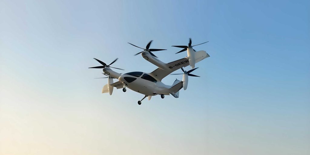
The tilt-rotor concept is one of the most mature hybrid configurations. It utilizes rotors mounted on nacelles at the wingtips (or occasionally on the fuselage) that can be pivoted relative to the airframe. For vertical flight and hover, the rotors are oriented vertically, acting similarly to helicopter rotors to provide lift. To transition to forward flight, the nacelles and their integrated rotors are tilted forward. In the fully transitioned cruise state, the rotors are oriented horizontally, functioning as propellers that provide forward thrust while the wing generates the necessary lift. This configuration effectively uses a single propulsion system for both VTOL and cruise, aiming for mechanical simplicity and high cruise efficiency due to the unloaded wing in forward flight.
The fundamental force balance during hover for a tilt-rotor VTOL UAV can be described by equating total thrust to weight:
$$ T_{hover} = n \cdot C_T \cdot \rho \cdot A \cdot (\Omega R)^2 = W $$
where $n$ is the number of rotors, $C_T$ is the thrust coefficient, $\rho$ is air density, $A$ is rotor disk area, $\Omega$ is rotational speed, $R$ is rotor radius, and $W$ is the vehicle weight. During cruise, the required thrust is significantly lower and is balanced by the aircraft drag:
$$ T_{cruise} = D = \frac{1}{2} \rho V^2 S C_D $$
where $V$ is cruise velocity, $S$ is wing reference area, and $C_D$ is the total drag coefficient.
2. Tilt-Duct VTOL UAV
The tilt-duct VTOL UAV is a variation of the tilt-rotor concept where the rotors are enclosed within annular ducts or shrouds. The entire ducted fan assembly is tilted. The duct serves multiple purposes: it contains the rotor tip vortices, potentially increasing thrust efficiency in hover by reducing tip losses and improving safety. Aerodynamically, the duct itself can generate lift (or negative lift) depending on the inflow conditions, adding complexity to the force balance. Furthermore, the duct offers opportunities for better aerodynamic integration with the wing or fuselage, potentially reducing interference drag. The working principle for mode transition is identical to the tilt-rotor; the primary differences lie in the aerodynamic behavior and performance of the ducted propulsion unit.
The thrust of a ducted fan in hover can be modeled with an augmented thrust coefficient that accounts for duct effects:
$$ T_{duct} = C_{T,duct} \cdot \rho \cdot A_{fan} \cdot (\Omega R_{fan})^2 $$
where $C_{T,duct}$ is typically higher than the $C_T$ of an isolated rotor of similar geometry due to the suppression of tip vortices and the contraction of the wake. However, this benefit may be offset by increased weight and parasitic drag in forward flight.
3. Dual-System VTOL UAV
Also known as a lift-plus-cruise configuration, the dual-system VTOL UAV employs two distinct and dedicated propulsion systems. One set of lift rotors or fans, often fixed in a vertical orientation, is used exclusively for VTOL and hover. A separate, independent propulsion system, such as a tractor or pusher propeller or a jet engine, provides thrust for forward cruise. This configuration decouples the design requirements for the two flight regimes. The lift system can be optimized for high static thrust, while the cruise system is optimized for propulsive efficiency at high speed. The transition involves gradually reducing power to the lift system as airspeed increases and wing lift becomes sufficient, while simultaneously increasing power to the cruise propulsion system.
The key design equations highlight the segregation. Hover thrust requirement remains: $T_{lift} = W$. Cruise thrust is provided by the separate system: $T_{cruise} = D$. The primary penalty is the “dead weight” of the inactive propulsion system during each flight phase. The total weight can be expressed as:
$$ W_{total} = W_{empty} + W_{payload} + W_{lift\_system} + W_{cruise\_system} + W_{energy} $$
where $W_{lift\_system}$ and $W_{cruise\_system}$ are largely parasitic during cruise and hover, respectively.
| Configuration | VTOL Mechanism | Cruise Mechanism | Primary Advantage | Primary Disadvantage |
|---|---|---|---|---|
| Tilt-Rotor | Tilting rotors/propellers | Same rotors as propellers | Single, efficient propulsion system for cruise | Complex aero-mechanical interactions; transition control |
| Tilt-Duct | Tilting ducted fan assemblies | Same ducts as propulsive units | Potential hover efficiency & safety; better integration | Increased weight & drag; complex duct aerodynamics |
| Dual-System | Dedicated lift rotors/fans | Dedicated cruise propeller/engine | Simplified control; decoupled design optimization | Dead weight penalty; higher empty weight |
Aerodynamic Design Analysis and Research Progress
The aerodynamic design of a VTOL UAV is profoundly interdisciplinary, involving rotor aerodynamics, wing aerodynamics, and crucially, their interactions. Significant research efforts have been devoted to understanding and optimizing these aspects.
Aerodynamic Interactions and Challenges
The co-existence of rotating and fixed aerodynamic surfaces in close proximity leads to complex interference phenomena that dominate the design and performance of VTOL UAVs.
For Tilt-Rotor/Tilt-Duct VTOL UAVs: In hover, the rotor downwash impinges on the wing and fuselage. This can cause a “fountain effect,” where downwash flows outward along the wing surface and upwards at the wing-fuselage junction, creating unsteady loads and potentially degrading rotor performance by altering its inflow. The download on the wing can be significant, requiring additional rotor thrust to compensate, which is inefficient. The interference can be modeled as a modification to the effective inflow velocity at the rotor disk:
$$ v_i’ = v_i + \Delta v_{interference} $$
where $v_i$ is the ideal induced velocity and $\Delta v_{interference}$ represents the velocity perturbation due to airframe interaction.
During transition and cruise, the aerodynamic interaction remains critical. The wake from the forward-tilted rotor/wing interaction can lead to unsteady periodic loading on the wing, potentially exciting aeroelastic instabilities. Furthermore, the rotor slipstream modifies the effective flow field over the wing and tail surfaces, affecting control authority and stability derivatives. The drag of the vehicle in cruise is a sum of components:
$$ C_D = C_{D,0} + C_{D,i} + C_{D,rotor} + C_{D,interference} $$
where $C_{D,0}$ is zero-lift drag, $C_{D,i}$ is induced drag, $C_{D,rotor}$ is rotor drag (windmilling or stopped), and $C_{D,interference}$ is the additional drag due to adverse aerodynamic interference.
For Dual-System VTOL UAVs: A key interaction for lift-fan based designs is the “suckdown” and “fountain” effect during hover. The lift fan draws air from above, creating a low-pressure region on the upper surface of the wing or fuselage, which results in a download force. The exiting jet may also impinge on the lower surface, creating an upward “blockage” force and complex vortex systems. The net effect is a reduction in lift fan thrust efficiency. Computational Fluid Dynamics (CFD) and wind tunnel testing are essential tools for quantifying these effects. Research has shown that careful shaping of the inlet and integration of guide vanes can mitigate losses and improve flow uniformity into the fan.
| Flight Regime | Dominant Interaction | Effect on VTOL UAV | Research Focus |
|---|---|---|---|
| Hover | Rotor downwash on airframe (Download/Fountain effect) | Reduces net lift; causes unsteady vibrations | CFD analysis of flow fields; design of airframe to deflect downwash |
| Transition | Changing rotor wake direction & strength on control surfaces | Highly nonlinear dynamics; challenging flight control | System identification; robust/adaptive control law development |
| Cruise | Rotor slipstream/wake interaction with wing & tail | Affects stability derivatives & control power; may cause buffet | High-fidelity aerodynamic modeling; wind-tunnel validation |
| Ground Effect | Interaction of downwash/jets with ground plane | Increases thrust efficiency near ground but can cause instability | Modeling of ground vortex formation; control for landing |
Research Methodologies and Advancements
Advancements in the design of VTOL UAVs have been propelled by sophisticated analysis tools.
Computational Fluid Dynamics (CFD): High-fidelity CFD, employing Reynolds-Averaged Navier-Stokes (RANS) or hybrid RANS-LES methods, has become indispensable. It is used to simulate the complex, viscous, turbulent, and often unsteady flow fields around VTOL UAVs in various flight conditions. Studies have successfully visualized and quantified the fountain effect, wake impingement, and separation phenomena. For ducted fans, CFD helps analyze lip separation at high angles of attack and the internal flow dynamics. Optimization algorithms coupled with CFD are used for shape optimization of wings, ducts, and rotor blades to maximize integrated performance.
Flight Dynamics Modeling: The equations of motion for a VTOL UAV are derived from Newton-Euler equations, but the aerodynamic force and moment coefficients ($C_X, C_Y, C_Z, C_l, C_m, C_n$) are complex functions of airspeed, angle of attack, sideslip, rotor tilt angle, and rotor thrust. System identification techniques, often using data from CFD or wind tunnel tests, are employed to develop reduced-order models suitable for flight control design. The transition phase dynamics are particularly challenging to model accurately.
Wind Tunnel Testing: Experimental validation remains crucial. Specialized wind tunnel tests are conducted to measure forces, moments, and surface pressures on scaled models. Particle Image Velocimetry (PIV) is used to capture detailed flow field structures. Testing covers the full range: from static hover (with ground plane simulation) through transition speeds to cruise conditions.
Critical Challenges and Future Research Directions
Despite significant progress, several persistent challenges must be addressed to unlock the full potential of VTOL UAVs.
1. Aerodynamic Configuration Design and Multidisciplinary Optimization (MDO)
The design of a VTOL UAV is a quintessential MDO problem. Aerodynamic efficiency, structural weight, propulsion system performance, and flight dynamics are deeply coupled. Future research should focus on developing efficient MDO frameworks that can explore novel configurations beyond the three classic types. Promising concepts include blended-wing-body (BWB) VTOL UAVs with distributed electric propulsion (DEP) and integrated lift fans. The BWB platform offers high aerodynamic efficiency and large internal volume, facilitating the embedding of propulsion systems. The objective function in such an MDO problem might be to minimize total energy consumption for a mission profile:
$$ \min J = \int_{t_0}^{t_f} P_{total}(t) \, dt $$
subject to constraints on stability, control authority, structural limits, and acoustic signature.
2. Flight Stability and Control, Especially During Transition
The transition corridor—the range of airspeeds where the vehicle can safely convert between flight modes—is narrow and fraught with stability risks. As the rotors tilt or as lift is transferred from rotors to the wing, the vehicle’s center of pressure, control derivatives, and inertia properties change dramatically. This requires robust, adaptive, or gain-scheduled control laws. Future work must integrate high-fidelity aerodynamic models (capturing cross-coupling and interference effects) into real-time capable flight dynamics models to design and validate controllers that can handle failures and atmospheric disturbances during this critical phase.
3. Crosswind and Disturbance Rejection
Crosswinds present a severe challenge, particularly during low-speed VTOL operations. For a tilt-rotor VTOL UAV, a crosswind can cause significant asymmetric loading on the rotors and wings, leading to strong rolling moments and control issues. For ducted fans, crosswind can induce flow separation at the duct lip, leading to thrust degradation and unsteady moments. The aerodynamic forces in crosswind are highly nonlinear. Research is needed to thoroughly characterize crosswind effects through CFD and testing and to develop control strategies that actively compensate for these disturbances, enabling reliable operation in urban and maritime environments.
4. Structural Lightweight and Aeroelastic Design
VTOL UAVs incur a weight penalty from the VTOL machinery (tilt mechanisms, additional rotors/fans). This “dead weight” directly reduces payload capacity and cruise efficiency. Future development must leverage advanced materials (composites, additive manufacturing) and structural optimization techniques (topology optimization) to achieve extreme lightweight designs. Furthermore, aeroelastic interactions, such as rotor-wing coupled flutter in tilt-rotors, must be analyzed and designed against. The integration of active aeroelastic control or morphing structures could provide avenues for weight reduction and performance adaptation across flight regimes.
Conclusion
The field of VTOL UAV aerodynamic design is vibrant and rapidly evolving, driven by burgeoning applications in logistics, surveillance, and urban air mobility. The tilt-rotor, tilt-duct, and dual-system configurations each offer distinct pathways to achieving hybrid flight capabilities, yet all grapple with the core complexities of aerodynamic interference, transition dynamics, and system integration. The performance and viability of any VTOL UAV are fundamentally dictated by the elegance and efficiency of its aerodynamic layout. Continued advancement relies on the synergistic application of high-fidelity computational analysis, innovative multidisciplinary design optimization, and rigorous experimental validation. Overcoming the persistent challenges in stability, crosswind operation, and structural efficiency will be pivotal. As these technological hurdles are addressed, VTOL UAVs are poised to transition from specialized platforms to ubiquitous tools, reshaping the boundaries of unmanned flight and enabling mission profiles previously considered impractical or impossible for a single vehicle. The ongoing research into novel configurations, such as blended-wing-body designs with integrated propulsion, suggests a future where the distinctions between lifting surfaces and propulsion devices become increasingly blurred, leading to truly optimized hybrid aerial vehicles.