The quest for unmanned aerial systems that combine the flexibility of rotary-wing platforms with the efficiency and speed of fixed-wing aircraft has led to significant interest in Vertical Take-Off and Landing (VTOL) configurations. Among these, the tail-sitter VTOL drone presents a compelling and mechanically simple solution. This configuration takes off and lands on its tail, hovering like a multi-rotor, before transitioning to wing-borne, high-speed forward flight. My research focuses on the aerodynamic characterization of such a platform, particularly under the complex flow conditions encountered during all flight phases, including strong wind disturbances. While wind tunnel testing offers high fidelity, it is often prohibitive in terms of cost and time for iterative design. Therefore, I employ Computational Fluid Dynamics (CFD) as a powerful and efficient tool to simulate and analyze the aerodynamic behavior of a custom-designed quad-rotor tail-sitter VTOL drone across a wide range of angles of attack and sideslip.
The primary objective is to obtain detailed aerodynamic coefficient data—lift, drag, and moments—over large angular ranges. This data is crucial not only for assessing the performance and stability of the initial design but also for informing subsequent optimization and, most importantly, for developing robust flight control algorithms capable of handling transitions and wind gusts. Existing studies often limit analysis to small angles of attack relevant to cruise flight, but a comprehensive understanding of a tail-sitter VTOL drone requires exploring its behavior at angles from 0° (level flight) to 90° (hover) and beyond, as well as under lateral flow conditions simulating crosswinds.
VTOL Drone Configuration and Design Philosophy
The design process began with defining key operational requirements for the tail-sitter VTOL drone. The goal was to create a platform capable of carrying a meaningful payload, operating efficiently in cruise, and demonstrating resilience in windy conditions. Key design drivers included compact size for portability, sufficient power for controlled hover and transition, and an aerodynamic shape efficient for forward flight.
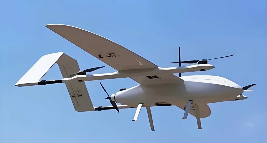
The core layout is a quad-rotor in an “X” configuration, chosen for its superior controllability and authority in generating control moments, which is essential for stabilization, especially in wind. To enhance aerodynamic efficiency, the wing incorporates winglets, forming a combined “Y” structure when viewed from the front. This design aims to reduce induced drag during cruise and improve directional stability. All major components—flight controller, battery, payload—are concentrated along the fuselage axis to minimize rotational inertia, simplifying attitude control. The airframe is designed without traditional aerodynamic control surfaces (ailerons, elevator, rudder), relying solely on differential rotor thrust for all attitude and flight path control.
A weight estimation was conducted to size the propulsion system. The total take-off mass was estimated using a component build-up method, resulting in a target of approximately 1,685 grams. To ensure a thrust-to-weight ratio greater than 2:1 in hover, the propulsion system was selected to provide a total static thrust exceeding 3,600 grams. The aerodynamic geometry was carefully selected; a high-lift, low-Reynolds number airfoil was chosen for the main wing to maintain performance at the intended cruise speed, while a symmetrical airfoil was used for the winglets. The primary geometric parameters of the designed VTOL drone are summarized in Table 1.
| Parameter | Value |
|---|---|
| Wingspan | 1.014 m |
| Reference Wing Area | 0.14438 m² |
| Main Wing Root Chord | 0.220 m |
| Main Wing Tip Chord | 0.156 m |
| Winglet Height | 0.280 m |
| Fuselage Length | 0.518 m |
| Estimated Take-off Mass | ~1.69 kg |
Computational Fluid Dynamics Methodology
To study the aerodynamic characteristics of this VTOL drone, a CFD-based approach was adopted. The process involves creating a digital model of the aircraft, discretizing the surrounding fluid domain into a mesh, and solving the governing equations of fluid flow.
The fundamental equations governing the flow are the Reynolds-Averaged Navier-Stokes (RANS) equations. For an incompressible, steady-state flow, the conservation of momentum is expressed as:
$$
\rho (\mathbf{u} \cdot \nabla) \mathbf{u} = -\nabla p + \mu \nabla^2 \mathbf{u} + \mathbf{S}
$$
where $$\rho$$ is the fluid density, $$\mathbf{u}$$ is the velocity vector, $$p$$ is the static pressure, $$\mu$$ is the dynamic viscosity, and $$\mathbf{S}$$ represents source terms. The flow around a VTOL drone, especially at high angles of attack, is inherently turbulent. To model the effects of turbulence, the Shear Stress Transport (SST) $$k-\omega$$ two-equation model was selected. This model is well-regarded for its accuracy in predicting flow separation under adverse pressure gradients, which is critical for analyzing stall behavior. The transport equations for turbulent kinetic energy ($$k$$) and specific dissipation rate ($$\omega$$) are:
$$
\begin{aligned}
\frac{\partial (\rho k)}{\partial t} + \frac{\partial (\rho u_j k)}{\partial x_j} &= \tilde{P}_k – \beta^* \rho k \omega + \frac{\partial}{\partial x_j} \left[ (\mu + \sigma_k \mu_t) \frac{\partial k}{\partial x_j} \right] \\
\frac{\partial (\rho \omega)}{\partial t} + \frac{\partial (\rho u_j \omega)}{\partial x_j} &= \frac{\gamma}{\nu_t} \tilde{P}_k – \beta \rho \omega^2 + \frac{\partial}{\partial x_j} \left[ (\mu + \sigma_{\omega} \mu_t) \frac{\partial \omega}{\partial x_j} \right] + D_{\omega}
\end{aligned}
$$
Here, $$\tilde{P}_k$$ is the production rate of turbulent kinetic energy, $$\mu_t$$ is the turbulent viscosity, and $$D_{\omega}$$ is the cross-diffusion term. The constants ($$\beta^*, \beta, \gamma, \sigma_k, \sigma_{\omega}$$) are model coefficients.
The 3D CAD model of the VTOL drone was simplified for computational efficiency—removing small protrusions like antennas and representing motors/propellers as streamlined spinners. The computational domain was a large cube, 11 meters on each side, with the drone positioned at its center. An unstructured tetrahedral mesh was generated, with refined sizing on the drone’s surface to capture boundary layer effects and gradients. The final mesh consisted of approximately 3.58 million cells. Boundary conditions were set as follows: a velocity inlet for the incoming flow, a pressure outlet, symmetry planes for the domain sides, and no-slip walls for the drone surface. Simulations were performed using a pressure-based solver with the SIMPLE algorithm for pressure-velocity coupling and second-order upwind discretization schemes. Air was modeled as an incompressible fluid with standard sea-level properties ($$\rho = 1.225\ kg/m^3$$, $$\mu = 1.789 \times 10^{-5}\ Pa \cdot s$$).
Aerodynamic Analysis Under Forward Flow Conditions
This scenario simulates the flow experienced during longitudinal flight, including level cruise, climb, descent, and the vertical hover/descent states. The angle of attack ($$\alpha$$) was varied from -5° to +185° at a freestream velocity of 15 m/s, with sideslip angle ($$\beta$$) set to 0°. The forces and moments are presented in coefficient form, normalized by dynamic pressure ($$q = \frac{1}{2} \rho V^2$$), reference area ($$S_{ref}$$), and reference length (mean aerodynamic chord, $$\bar{c}$$, for pitching moment). The standard aerodynamic coefficient definitions are used:
$$
C_L = \frac{L}{q S_{ref}}, \quad C_D = \frac{D}{q S_{ref}}, \quad C_m = \frac{M_y}{q S_{ref} \bar{c}}
$$
The resulting curves for lift coefficient ($$C_L$$), drag coefficient ($$C_D$$), lift-to-drag ratio ($$C_L/C_D$$), and pitching moment coefficient ($$C_m$$) are central to understanding the VTOL drone’s longitudinal behavior.
For angles of attack between -5° and +10°, the lift coefficient exhibits a linear relationship with $$\alpha$$, which can be modeled as:
$$
C_L = C_{L_0} + C_{L_\alpha} \cdot \alpha
$$
where $$C_{L_\alpha}$$ is the lift curve slope. The maximum lift coefficient of approximately 1.26 is reached at $$\alpha \approx 15^\circ$$, indicating the stall angle. Beyond this point, $$C_L$$ drops significantly. At $$\alpha = 90^\circ$$, simulating a direct headwind in hover, the lift coefficient is near zero, and the drag coefficient peaks at its maximum value, as the body presents its largest frontal area. The lift-to-drag ratio, a key metric for cruise efficiency, reaches a maximum of about 10.1 at $$\alpha = 7^\circ$$. This angle represents the optimal cruise condition for this VTOL drone, balancing lift production with drag penalty.
The pitching moment coefficient reveals the longitudinal static stability characteristics. The slope of the $$C_m$$ vs. $$\alpha$$ curve in the linear region is positive, indicating negative longitudinal static stability (i.e., the vehicle is statically unstable in pitch). This is a common trait in many flying wing or tail-less configurations and necessitates active stabilization via the flight control system. The moment curve shows significant nonlinearity post-stall and at very high angles of attack, which must be accounted for in controller design, especially for transition and recovery maneuvers.
| Parameter | Value / Condition |
|---|---|
| Maximum Lift Coefficient, $$C_{L_{max}}$$ | ~1.26 at $$\alpha \approx 15^\circ$$ |
| Stall Angle | ~15° |
| Optimal Cruise AoA (Max $$C_L/C_D$$) | ~7° |
| Maximum Lift-to-Drag Ratio | ~10.1 |
| Zero-Lift Drag Coefficient, $$C_{D_0}$$ | ~0.05 (approx., from curve) |
| Longitudinal Static Stability (Linear Region) | Negative (Unstable) |
Aerodynamic Analysis Under Lateral Flow Conditions
This analysis simulates the effect of a pure crosswind on the VTOL drone, which is critical for understanding its behavior during hover or cruise in windy conditions. The sideslip angle ($$\beta$$) was varied from 0° to 90° at a freestream velocity of 5 m/s, with the angle of attack fixed at 0°. The relevant force and moment coefficients are the side force coefficient ($$C_Y$$), drag coefficient ($$C_D$$), yawing moment coefficient ($$C_n$$), and rolling moment coefficient ($$C_l$$).
The results show that for small sideslip angles ($$\beta < 10^\circ$$), the side force and yawing moment vary approximately linearly:
$$
C_Y \approx C_{Y_\beta} \cdot \beta, \quad C_n \approx C_{n_\beta} \cdot \beta
$$
The derivative $$C_{Y_\beta}$$ is negative, indicating that a positive sideslip (wind from the right) generates a negative side force (to the left). The derivative $$C_{n_\beta}$$ is positive, denoting weathercock or directional stability—the yawing moment tends to align the vehicle’s nose into the wind. However, the magnitude of $$C_{n_\beta}$$ is relatively small for this VTOL drone configuration. The rolling moment coefficient ($$C_l$$) is also generated due to asymmetric lift on the wings in sideslip. For this design, a positive $$\beta$$ generally produces a negative $$C_l$$, inducing a left-rolling moment.
As the sideslip angle increases beyond 10°, all coefficients exhibit strong nonlinearity. The drag increases substantially, and complex flow interactions around the fuselage and winglets lead to non-monotonic changes in the moment coefficients. This nonlinear lateral-directional behavior at high sideslip angles presents a challenge for control system design, as the vehicle’s response to crosswind disturbances will not be linear across all wind intensities.
Aerodynamic Analysis Under Vertical Flow Conditions
This final scenario is specific to the VTOL drone’s hover mode. It investigates the forces and moments generated when wind impinges on the vehicle from various directions in the plane perpendicular to the hover attitude (i.e., the plane containing the wing span and fuselage vertical axis). The flow angle ($$\gamma$$) was varied from 0° (flow along the positive wing-span axis) to 90° (flow directly opposing the belly, akin to a vertical updraft). The freestream velocity was set to 5 m/s. The analysis focuses on the resultant force magnitude and the resulting pitching ($$M$$), rolling ($$L$$), and yawing ($$N$$) moments in physical units (Newtons, Newton-meters).
The data reveals that the resultant aerodynamic force is primarily drag-dominated, increasing monotonically with the flow angle $$\gamma$$ until it plateaus near $$\gamma = 70^\circ$$. The maximum force of about 3.8 N represents a significant disturbance for a hovering VTOL drone with a weight of ~16.5 N, equivalent to a steady wind of 5 m/s creating a lateral acceleration disturbance. The moment trends are particularly instructive for control strategy. The rolling moment shows a strong tendency to rotate the vehicle so that its belly faces the incoming wind, reaching a maximum at $$\gamma \approx 45^\circ$$. The pitching moment also acts to align the nose into the wind, but is weaker. The yawing moment is negligible.
This has a direct implication for flight control: actively controlling the hover attitude of the VTOL drone to keep its belly approximately aligned with the prevailing wind direction can minimize the destabilizing moments and reduce control effort. This “weathervaning” strategy leverages the natural aerodynamic stability in roll derived from the fuselage and winglet geometry.
| Flow Angle ($$\gamma$$) | Resultant Force (N) | Dominant Moment Tendency |
|---|---|---|
| 0° (From Side) | ~0.8 | Weak Rolling |
| 45° | ~3.5 | Strong Rolling (Belly to Wind) |
| 90° (Head-on to Belly) | ~3.8 | Pure Pitching (Nose Down) |
Discussion and Implications for VTOL Drone Design and Control
The comprehensive CFD analysis provides a detailed map of the aerodynamic properties of the tail-sitter VTOL drone across its entire flight envelope. The data confirms that the designed platform achieves a respectable cruise efficiency, with a maximum lift-to-drag ratio characteristic of small, clean UAVs. The identified optimal cruise angle of attack ($$7^\circ$$) serves as a key setpoint for the forward flight controller.
More critically, the analysis highlights the complex, nonlinear aerodynamic environment the vehicle must operate within, especially during hover, transition, and in wind. The longitudinal instability necessitates a continuous, active pitch stabilization system. The lateral-directional behavior, while showing mild natural weathercock stability at small angles, becomes highly nonlinear in strong crosswinds, demanding a robust multi-axis controller.
The findings from the vertical flow analysis offer a strategic insight: the inherent aerodynamic coupling can be used advantageously. By designing a control law that allows the hovering VTOL drone to weathervane slightly into the wind (prioritizing belly alignment), the disturbance moments can be significantly reduced, conserving control energy and improving stability margins. This is a direct application of aerodynamic data to control system synthesis.
Furthermore, the detailed coefficient tables and curves serve as a foundational dataset for higher-fidelity flight dynamics modeling and simulation. The nonlinear functions $$C_L(\alpha), C_D(\alpha), C_m(\alpha)$$, and their lateral-directional counterparts can be implemented in a six-degree-of-freedom simulation to test and refine autopilot algorithms for transition, wind rejection, and failure recovery before actual flight tests.
Conclusion
This study successfully demonstrates the application of Computational Fluid Dynamics as an effective methodology for the extensive aerodynamic characterization of a tail-sitter VTOL drone. By simulating flows from forward, lateral, and vertical directions across large angular ranges, a complete picture of the vehicle’s static aerodynamic properties has been developed. The results confirm the feasibility of the initial design for efficient cruise flight while unequivocally revealing the challenges associated with stability and control, particularly in high-angle-of-attack and crosswind conditions. The derived aerodynamic coefficients, with their pronounced nonlinearities, provide the essential data required for the next critical phase: the design and simulation of a robust, nonlinear flight control system capable of managing the unique and demanding flight profile of this agile VTOL drone from vertical take-off through high-speed cruise and back to vertical landing, even in the presence of significant atmospheric disturbances.