The transition phase for Vertical Take-Off and Landing (VTOL) drones, particularly tail-sitter configurations, presents one of the most challenging flight regimes. Unlike pure multirotors or fixed-wing aircraft, these hybrid vehicles must execute a controlled rotation of their airframe to shift from hovering flight to forward cruise and vice-versa. This maneuver is characterized by high angles of attack, significant nonlinearities in aerodynamics and control effectiveness, and tight coupling between longitudinal states. The performance, safety, and energy efficiency of the entire mission heavily depend on the quality of the transition trajectory. A poorly designed trajectory can lead to excessive altitude loss or gain, actuator saturation, loss of control authority, or even a stall. Therefore, developing robust and feasible transition trajectory optimization methods is paramount for the reliable operation of advanced VTOL drones.
Traditional optimal control methods, while mathematically rigorous, often yield transition trajectories with low practical feasibility and poor robustness. This is primarily because they rely on precise mathematical models, which are difficult to obtain accurately for complex VTOL drone configurations, especially when accounting for propeller-wing interactions. Furthermore, many methods optimize for a single objective—like minimal altitude change or time—without considering the necessary margin on actuator usage. A trajectory that commands actuators near their limits leaves no room for the control system to counteract disturbances, making the flight vulnerable to gusts or model inaccuracies. Our research addresses these critical gaps by introducing a novel framework that synergizes the concept of a transition corridor with a multi-objective optimal control formulation, specifically tailored for tail-sitter VTOL drones.
The core of our approach lies in first defining a safe flight envelope for the VTOL drone during transition—the transition corridor. Inspired by methodologies applied to tilt-rotor aircraft, this corridor delineates all combinations of airspeed and pitch angle where stable, trim flight is possible under a comprehensive set of physical and safety constraints. By restricting the transition trajectory to lie within this corridor, we inherently ensure a baseline level of feasibility and safety. Subsequently, we define an ideal path within this corridor that maximizes the distance to the boundaries, thus providing the greatest robustness against model errors. Finally, we solve a trajectory optimization problem that tracks this ideal path while explicitly penalizing actuator usage and minimizing altitude deviation, resulting in a practical, high-performance transition trajectory for the VTOL drone.
Problem Statement and Dynamics of a Tail-Sitter VTOL Drone
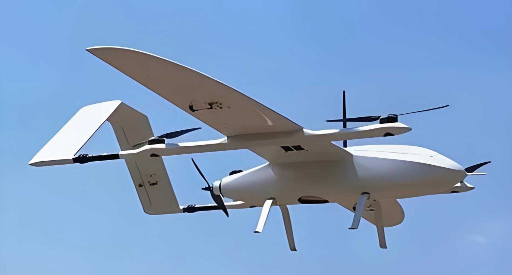
The tail-sitter VTOL drone operates by orienting its fuselage vertically for takeoff, hover, and landing, and horizontally for forward flight. Transition involves pitching the entire airframe between these two attitudes. We focus on a dual-rotor configuration, where two propellers provide thrust and differential thrust can be used for yaw control, while elevons (combined elevator and aileron surfaces) provide pitch and roll control. The primary challenge in modeling this VTOL drone is the significant difference in aerodynamic conditions experienced by the wing sections inside the propeller slipstream versus those outside it.
We define two key coordinate frames: the body frame \(F_B\) (origin at the Center of Gravity, \(x_B\) forward, \(y_B\) right, \(z_B\) down) and the inertial frame \(F_I\) (North-East-Down). The longitudinal dynamics are derived from the Newton-Euler equations. The general 6-DoF equations of motion can be simplified for longitudinal analysis as:
$$
\begin{aligned}
m \dot{V}_I^g &= R_I^B (F^B_e + F^B_d) \\
J \dot{\omega}^B &= -[\omega^B]_\times J \omega^B + M^B_e + M^B_d \\
\dot{P} &= V_I^g
\end{aligned}
$$
where \(m\) is mass, \(V_I^g\) is the ground speed vector, \(R_I^B\) is the rotation matrix from \(F_B\) to \(F_I\), \(\omega^B\) is the body angular rate vector, \(J\) is the inertia matrix, \(P\) is the position vector, and \(F_d, M_d\) represent unknown disturbance forces/moments. The known forces and moments \(F_e, M_e\) comprise aerodynamic, propulsive, and gravitational components:
$$
\begin{aligned}
F^B_e &= F_{aero} + F_T + G^B \\
M^B_e &= M_{aero} + M_T
\end{aligned}
$$
The unique “split-flow” aerodynamic modeling is crucial for an accurate representation of this VTOL drone. The wing is divided into six regions: four “free-stream” regions (L3, L1, R1, R3) and two “slip-stream” regions (L2, R2) directly behind the propellers.
| Region Type | Affected Sections | Inflow Velocity |
|---|---|---|
| Free-Stream | L3, L1, R1, R3 | \(V^B_{a,out} = R^I_B(V^g_I – V^w_I)\) |
| Slip-Stream | L2, R2 | \(V^B_{a,in} = V^B_{a,out} + V^B_{induce}\) |
Here, \(V^w_I\) is the wind velocity and \(V^B_{induce} = [-u_0, 0, 0]^T\) is the induced velocity from the propeller, calculated using momentum theory:
$$
u_0 = \frac{v_0 + \sqrt{v_0^2 + 2T_P / (\rho S)}}{2} \cdot \frac{\sqrt{l^2 + R^2}}{l + \sqrt{l^2 + R^2}}
$$
where \(T_P\) is propeller thrust, \(\rho\) is air density, \(S\) is propeller disk area, \(R\) is propeller radius, \(l\) is the distance from the propeller to the aerodynamic center of the slip-stream region, and \(v_0\) is the component of \(V^B_{a,out}\) along the propeller axis.
The angle of attack differs significantly between regions:
$$
\alpha_{out} = \arctan\left(\frac{V^B_{a,out,z}}{V^B_{a,out,x}}\right), \quad \alpha_{in} = \arctan\left(\frac{V^B_{a,in,z}}{V^B_{a,in,x}}\right)
$$
The total aerodynamic lift \(L\), drag \(D\), and pitching moment \(M\) are summations of contributions from each region \(n\):
$$
\begin{aligned}
L &= \sum_{n=1}^{6} \frac{1}{2} \rho v_n^2 S_{w,n} \left( C_{L_n}(\alpha) + C_{L_q} \frac{\bar{c}}{2v_n} q + C_{L_\delta} \frac{S_{e,n}}{S_{w,n}} \delta_e \right) \\
D &= \sum_{n=1}^{6} \frac{1}{2} \rho v_n^2 S_{w,n} \left( C_{D_n}(\alpha) + C_{D_q} \frac{\bar{c}}{2v_n} q + C_{D_\delta} \frac{S_{e,n}}{S_{w,n}} \delta_e \right) \\
M &= \sum_{n=1}^{6} \frac{1}{2} \rho v_n^2 \bar{c} S_{w,n} \left( C_{M_n}(\alpha) + C_{M_q} \frac{\bar{c}}{2v_n} q + C_{M_\delta} \frac{S_{e,n}}{S_{w,n}} \delta_e \right)
\end{aligned}
$$
Here, \(v_n\) is the local airspeed magnitude for region \(n\), \(S_{w,n}\) and \(S_{e,n}\) are the wing and control surface areas, \(\bar{c}\) is the mean aerodynamic chord, \(q\) is the pitch rate, \(\delta_e\) is the elevon deflection, and \(C_{*}\) are the aerodynamic coefficients. The longitudinal equations of motion for the VTOL drone in the body frame are:
$$
\begin{aligned}
\dot{u} &= -g \sin\theta – w q + (F_{e,x}^B + F_{T1}+F_{T2})/m \\
\dot{w} &= g \cos\theta + u q + F_{e,z}^B/m \\
\dot{\theta} &= q \\
\dot{q} &= M_{e,y}^B / I_{yy} \\
\dot{X}_I &= u \cos\theta + w \sin\theta \\
\dot{Z}_I &= -u \sin\theta + w \cos\theta
\end{aligned}
$$
where \(u, w\) are body-frame velocities, \(\theta\) is the pitch angle, and \(X_I, Z_I\) are inertial position components.
Transition Corridor Design for VTOL Drones
The transition corridor is defined as the set of all feasible steady-state flight conditions (trim states) during the transition maneuver for the VTOL drone. It maps the permissible airspeed \(V\) (magnitude of \(V^B_{a,out}\)) against the vehicle’s pitch angle \(\theta\). A point \((V, \theta)\) lies inside the corridor if there exists a combination of control inputs (thrust \(T\) and elevon deflection \(\delta_e\)) that satisfies the force and moment equilibrium equations while adhering to all physical and safety constraints.
The constraints defining the corridor for the forward transition (hover to cruise) are:
| Constraint Category | Mathematical Expression | Physical Rationale |
|---|---|---|
| Longitudinal Force | \(F^B_{e,x} \ge 0\) | Net forward acceleration required. |
| Vertical Force | \(F^B_{e,z} \le 0\) | Net force must counterweight, no downward push. |
| Moment & Kinematics | \(M^B_{e,y}=0, \quad q \le 0\) | Trim condition, nose-down rotation. |
| Vertical Rate | \(-3 \le \dot{Z}_I \le 0 \, \text{m/s}\) | Limit climb/sink rate for safety. |
| Angle of Attack | \(0 \le \alpha_{out} \le \alpha_{\text{max}}\) | Prevent stall (\(\alpha_{\text{max}} \approx 80\%\) of stall \(\alpha\)). |
| Actuator Limits | \(0 \le T \le T_{\text{max}}, \quad |\delta_e| \le \delta_{\text{max}}\) | Physical bounds of the VTOL drone. |
| Airspeed | \(V \in [0, V_{\text{max}}]\) | Operational envelope. |
For the backward transition (cruise to hover), the constraints are similar but with key sign changes: \(F^B_{e,x} \le 0\) (deceleration) and \(q \ge 0\) (nose-up rotation). By solving the trim equations subject to these constraints across a grid of \(V\) and \(\theta\) values, we populate the set of feasible points. The boundary of this set forms the transition corridor. The corridor for a representative VTOL drone shows a narrowing “throat” at moderate pitch angles and speeds, indicating the most challenging part of the transition where control authority is minimal.
Model inaccuracies directly impact the corridor’s size and shape. For instance, if the actual lift coefficient \(C_L\) is lower than modeled, the corridor shrinks, particularly raising the minimum allowable pitch angle at a given speed. If the pitching moment coefficient \(C_M\) is more negative than expected, the backward transition corridor becomes narrower. Therefore, any trajectory planned using the nominal corridor must account for this uncertainty by staying away from the boundaries.
Target and Optimal Transition Trajectory Generation
Within the transition corridor, we first define a Target Transition Trajectory. This is an ideal path, \(\theta^*(V)\), that maximizes the safety margin against the corridor boundaries. We define a margin function \(\mathcal{M}(V)\) for a candidate trajectory \(\theta(V)\):
$$
\mathcal{M}(V) = \frac{|\theta(V) – \theta_{\min}(V)|}{ \theta_{\max}(V) – \theta_{\min}(V)} \cdot \frac{|\theta(V) – \theta_{\max}(V)|}{ \theta_{\max}(V) – \theta_{\min}(V)}
$$
where \(\theta_{\min}(V)\) and \(\theta_{\max}(V)\) are the lower and upper boundaries of the corridor at speed \(V\). The product form ensures the margin is zero at the boundaries and maximum at the centerline. The target trajectory is found by solving:
$$
\begin{aligned}
& \underset{\theta(V)}{\text{find}} \\
& \text{maximize} \quad J_{\text{targ}} = \int_{V_0}^{V_f} \mathcal{M}(V) \, dV \\
& \text{subject to} \quad \theta_{\min}(V) \le \theta(V) \le \theta_{\max}(V) \\
& \quad \quad \quad \quad \theta(V_0) = \theta_0, \quad \theta(V_f) = \theta_f
\end{aligned}
$$
This yields a trajectory that runs through the middle of the corridor, offering the greatest robustness for the VTOL drone against model errors.
Next, we formulate the Optimal Transition Trajectory problem. This is a full optimal control problem that finds the control time histories \(U^*(t) = [T^*(t), \delta_e^*(t)]\) guiding the VTOL drone from initial state \(\mathbf{x}_0\) to final state \(\mathbf{x}_f\), while tracking the target trajectory, minimizing altitude deviation and actuator usage, and respecting all dynamics and constraints. The cost function \(J\) incorporates multiple objectives:
$$
\begin{aligned}
J = & \underbrace{k_1 \int_{t_0}^{t_f} (h(t)-h_0)^2 dt}_{\text{Altitude Hold}} + \underbrace{k_2 \int_{V_0}^{V_f} (\theta(V)-\theta^*(V))^2 dV}_{\text{Corridor Tracking}} \\
& + \underbrace{k_3 \int_{t_0}^{t_f} \left[ \left(\frac{T(t)}{T_{\text{max}}}\right)^2 + \left(\frac{\delta_e(t)}{\delta_{\text{max}}}\right)^2 \right] dt}_{\text{Actuator Margin}} \\
& + \underbrace{\beta_u (u_f – u_{\text{des}})^2 + \beta_w (w_f)^2 + \beta_\theta (\theta_f – \theta_{\text{des}})^2}_{\text{Terminal State}}
\end{aligned}
$$
The complete optimization problem for the VTOL drone is:
$$
\begin{aligned}
& \underset{T(t), \, \delta_e(t)}{\text{minimize}} \quad J \\
& \text{subject to} \\
& \quad \text{Dynamics:} \quad \dot{\mathbf{x}}(t) = f(\mathbf{x}(t), T(t), \delta_e(t)) \quad (\text{Eqns. of Motion}) \\
& \quad \text{Initial/Final States:} \quad \mathbf{x}(t_0) = \mathbf{x}_0, \quad \mathbf{x}(t_f) = \mathbf{x}_f \\
& \quad \text{Path Constraints:} \quad \mathbf{x}(t) \in \mathcal{X}, \quad T(t) \in [0, T_{\text{max}}], \quad \delta_e(t) \in [-\delta_{\text{max}}, \delta_{\text{max}}] \\
& \quad \quad \quad \quad \quad \dot{Z}_I(t) \in [\dot{Z}_{\min}, \dot{Z}_{\max}], \quad t_f \in [t_{\min}, t_{\max}]
\end{aligned}
$$
This problem is transcribed into a Nonlinear Programming (NLP) problem using a direct collocation method and solved with a standard solver. The solution provides the optimal state trajectory \(\mathbf{x}^*(t)\) and the optimal control sequence \(U^*(t)\) for the VTOL drone’s transition.
Control Framework and Validation
The optimal control sequence \(U^*(t)\) is used as a feedforward command. To reject disturbances and model errors, a simple feedback loop is added. The combined control input for the elevon is:
$$
\delta_{e, cmd}(t) = \delta_e^*(t) + K_\theta (\theta^*(t) – \theta(t)) + K_q (q^*(t) – q(t))
$$
For thrust, a similar combination is used, blending feedforward thrust \(T^*(t)\) with feedback from altitude and speed controllers. This two-degree-of-freedom structure ensures both performance and robustness for the VTOL drone during the critical transition.
The proposed methodology was rigorously validated. First, Hardware-in-the-Loop (HITL) simulations were conducted, comparing our method against three others: the widely-used PX4 firmware’s linear transition, a minimum-altitude-change method, and an energy-optimal method. The key performance indicators are summarized below:
| Transition Method | Transition Time \(t_{trans}\) (s) | Max Altitude Change \(\Delta h_{max}\) (m) | Max Thrust Usage (% of \(T_{max}\)) | Max Actuator Usage (% of \(\delta_{max}\)) |
|---|---|---|---|---|
| Forward Transition (Hover to Cruise) | ||||
| PX4 Linear Method | 2.15 | 7.60 | 85.7 | 99.8 |
| Min-Altitude Method | 3.31 | 1.63 | 80.2 | 29.1 |
| Energy-Optimal Method | 3.09 | 3.87 | 82.6 | 32.6 |
| Our Corridor-Based Method | 2.88 | 3.93 | 83.9 | 46.7 |
| Backward Transition (Cruise to Hover) | ||||
| PX4 Linear Method | 3.51 | 7.51 | 78.3 | 48.9 |
| Min-Altitude Method | 0.80 | 2.13 | 99.6 | 99.8 |
| Energy-Optimal Method | 1.29 | 2.69 | 84.5 | 87.1 |
| Our Corridor-Based Method | 1.81 | 2.71 | 82.1 | 83.6 |
The results clearly show the trade-offs. While the min-altitude method excels at height keeping, it can demand excessively long transition times (forward) or lead to actuator saturation (backward), reducing robustness. The PX4 method, though fast, causes large, inefficient altitude excursions. Our corridor-based method for the VTOL drone consistently strikes a balanced compromise: it maintains moderate transition times, keeps altitude change within reasonable bounds, and crucially, avoids actuator saturation, thereby preserving control margin for robustness.
Furthermore, we define a trajectory error factor \(Q_e\) to measure how closely a flown trajectory follows the centerline (target) of the corridor:
$$
Q_e = \frac{1}{100} \sum_{r=0}^{20} \left( \theta_r(V) – \theta^*_r(V) \right)^2
$$
In both simulation and real-flight tests, our method achieved the lowest \(Q_e\) value, confirming that it best utilizes the safety margins built into the transition corridor for the VTOL drone, enhancing overall robustness.
Finally, the entire system was successfully demonstrated in full-scale autonomous flight tests with a custom-built tail-sitter VTOL drone. The vehicle reliably executed repeated forward and backward transitions, closely following the optimized trajectories. The flights confirmed the practical feasibility of the approach, with no instances of stall, severe altitude loss, or loss of control, even in the presence of mild wind disturbances.
Conclusion
This work presents a comprehensive and practical framework for optimizing the transition trajectory of tail-sitter VTOL drones. By integrating a physics-based transition corridor into the optimal control formulation, we address the core limitations of traditional methods. The corridor guarantees fundamental feasibility and provides a clear metric for robustness—the distance from its boundaries. The multi-objective optimization then synthesizes a trajectory that not only stays within this safe envelope but also actively manages critical flight parameters: it minimizes altitude deviation, tracks the safest path inside the corridor, and, most importantly, explicitly conserves actuator control margin.
The comparative analysis through high-fidelity HITL simulation and real-world flight tests validates the advantages of this approach. Unlike methods that optimize for a single, extreme performance point, our corridor-based method for the VTOL drone delivers balanced and robust performance. It avoids the excessive altitude changes of simple methods and the actuator saturation risks of aggressive minimum-time or minimum-altitude strategies. By ensuring the transition maneuver remains within the VTOL drone’s proven flight envelope and retaining ample control authority, this method significantly enhances the safety, reliability, and operational predictability of autonomous transition flights. This paves the way for more complex mission profiles and wider adoption of tail-sitter VTOL drone technology in demanding applications.