Vertical Take-Off and Landing (VTOL) drones represent a significant area of research, combining the endurance and speed of fixed-wing aircraft with the versatility of rotary-wing platforms. Among VTOL configurations, the tail-sitter, which takes off and lands on its tail, offers a mechanically simple solution but introduces profound control challenges. During the tail-sitter phases, the aircraft operates in a deeply stalled, near-vertical attitude where conventional aerodynamic control surfaces are ineffective. This necessitates the use of alternative control mechanisms, with thrust vectoring being a prominent and effective solution. This article delves into the comprehensive control methodologies for a thrust-vectored VTOL drone during tail-sitter vertical takeoff and landing, addressing critical issues in attitude representation, control law design, and the tightly coupled problem of altitude stabilization.
The core challenge in tail-sitter flight stems from the aircraft’s inherent instability when vertical, resembling an inverted pendulum. Small disturbances can lead to divergence if not actively and precisely controlled. Furthermore, the near-90-degree pitch orientation causes singularities in conventional Euler angle representations, complicating the feedback loop. The control authority relies entirely on vectored thrust, which couples forces and moments in a non-intuitive way, especially when compensating for engine-induced reaction torques. Finally, altitude control is not independent but is strongly coupled with attitude, as the vertical component of the total thrust is a function of the aircraft’s lean angle. This article presents a holistic approach: a composite horizontal/vertical Euler angle method for singularity-free attitude representation, a fast yet stable attitude controller, a novel iterative sensor fusion algorithm for robust altitude estimation, and a dedicated altitude controller designed to manage the strong attitude-altitude coupling. Experimental results from a prototype thrust-vectored VTOL drone validate the effectiveness of the proposed framework.
Dynamic Modeling of the Thrust-Vectored VTOL Drone
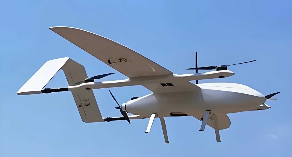
To lay the foundation for controller design, a simplified dynamic model of the VTOL drone during tail-sitter operation is established. Given the low airspeed and high angle of attack, aerodynamic forces are negligible compared to thrust and gravity. The model focuses on the forces and moments generated by the thrust-vectoring system. The VTOL drone configuration consists of a main ducted-fan engine providing primary thrust \(T\), and two auxiliary propeller engines providing supplemental thrust \(T_{\text{assist}}\) each for enhanced endurance. The main thrust is channeled through two vectored nozzles. The left and right nozzle deflections in the pitch plane are denoted \(\delta_{lp}\) and \(\delta_{rp}\), respectively. Both nozzles can also deflect collectively in the yaw plane by an angle \(\delta_{lry}\). The positive deflection directions are defined in the body frame.
The equations of motion are derived in the body frame. The force equations along the body x, y, and z axes are:
$$
\begin{aligned}
m(\dot{U} + QW – RV) &= -mg\sin\theta + \frac{T}{2}(\cos\delta_{lp} + \cos\delta_{rp})\cos\delta_{lry} + 2T_{\text{assist}}, \\[4pt]
m(\dot{V} + RU – PW) &= mg\sin\phi\cos\theta – \frac{T}{2}(\cos\delta_{lp} + \cos\delta_{rp})\sin\delta_{lry}, \\[4pt]
m(\dot{W} + PV – QU) &= mg\cos\phi\cos\theta + \frac{T}{2}\cos\delta_{lry}(\sin\delta_{lp} + \sin\delta_{rp}),
\end{aligned}
$$
where \(m\) is the mass, \(U, V, W\) are body-axis velocities, and \(\phi, \theta, \psi\) are the roll, pitch, and yaw Euler angles. The moment equations about the body axes are:
$$
\begin{aligned}
\dot{P}I_x &+ QR(I_z – I_y) – (\dot{R} + PQ)I_{xz} = \\
&-\frac{T}{2} l \cos\delta_{lry}(\sin\delta_{lp} – \sin\delta_{rp}) + M_K, \\[6pt]
\dot{Q}I_y &- PR(I_z – I_x) + (P^2 – R^2)I_{xz} = \\
&\frac{T}{2} d \cos\delta_{lry}(\sin\delta_{lp} + \sin\delta_{rp}), \\[6pt]
\dot{R}I_z &+ PQ(I_y – I_x) + (QR – \dot{P})I_{xz} = \\
&\frac{T}{2} d (\cos\delta_{lp} + \cos\delta_{rp}) \sin\delta_{lry}.
\end{aligned}
$$
Here, \(P, Q, R\) are body-axis angular rates, \(I_x, I_y, I_z\) are moments of inertia, \(I_{xz}\) is the product of inertia, \(l\) is half the distance between the two nozzles, \(d\) is the moment arm from the nozzle pivot line to the center of gravity, and \(M_K\) is the reaction torque from the main engine. For an electric ducted fan, it can be shown that the steady-state deflection \(\delta_{\text{anti T}}\) required to cancel \(M_K\) is constant, as \(M_K \propto T\) and the compensating moment is \(T l \sin\delta_{\text{anti T}}\).
Key system parameters for the experimental VTOL drone are summarized below.
| Parameter | Symbol | Value | Unit |
|---|---|---|---|
| Mass | \(m\) | 4.0 | kg |
| Wingspan | – | 0.96 | m |
| Length | – | 1.5 | m |
| Nozzle Moment Arm | \(d\) | ~0.15 | m |
| Half Nozzle Spacing | \(l\) | ~0.1 | m |
| Main Engine Max Thrust | \(T_{\text{max}}\) | ~60 | N |
| Nozzle Deflection Range | \(\delta_{lp}, \delta_{rp}\) | ±20 | deg |
| Yaw Deflection Range | \(\delta_{lry}\) | ±5 | deg |
Singularity-Free Attitude Representation for VTOL Drones
Conventional Euler angles (\(\phi, \theta, \psi\)) encounter a gimbal lock singularity when the pitch angle \(\theta\) approaches ±90°, which is precisely the operational state of a tail-sitter VTOL drone. While quaternions offer a singularity-free representation, their lack of direct geometric interpretation complicates intuitive controller design. We propose a composite Horizontal/Vertical Euler Angle method. The attitude is first obtained as a Direction Cosine Matrix (DCM) \(\mathbf{C}_b^n\) from sensor fusion. The standard “horizontal” Euler angles (subscript \(H\)), referenced to the conventional body frame, are:
$$
\theta_H = \arcsin(-c_{zx}), \quad \phi_H = \arctan\left(\frac{c_{zy}}{c_{zz}}\right), \quad \psi_H = \arctan\left(\frac{c_{yx}}{c_{xx}}\right).
$$
These become singular near \(\theta_H = 90°\). We therefore define a “vertical” body frame, rotated 90° about the body y-axis from the horizontal frame. The corresponding “vertical” Euler angles (subscript \(V\)) are:
$$
\theta_V = \arcsin(-c_{zz}), \quad \phi_V = \arctan\left(\frac{c_{zy}}{-c_{zx}}\right), \quad \psi_V = \arctan\left(\frac{c_{yz}}{c_{xz}}\right).
$$
The vertical representation moves the singularity to \(\theta_V = 0°\). The control system operates primarily in horizontal angles during level flight and switches to vertical angles during tail-sitter phases. The angular rates must also be transformed. In the horizontal frame, \([\omega_{Hx}, \omega_{Hy}, \omega_{Hz}] = [\omega_{gyro,x}, \omega_{gyro,y}, \omega_{gyro,z}]\). In the vertical frame, the mapping is \([\omega_{Vx}, \omega_{Vy}, \omega_{Vz}] = [\omega_{gyro,z}, \omega_{gyro,y}, -\omega_{gyro,x}]\). A hysteresis-based logic prevents chattering at the switch boundary.
| Mode Transition | Switch Condition |
|---|---|
| Horizontal → Vertical | Previous \(\theta_H < 60°\) AND Current \(\theta_H > 60°\) |
| Vertical → Horizontal | Previous \(\theta_H > 30°\) AND Current \(\theta_H < 30°\) |
Attitude Controller Design for the Unstable VTOL Drone
The tail-sitter VTOL drone is an inherently unstable system. The attitude controller must provide rapid disturbance rejection while strictly preventing overshoot and oscillation that could lead to divergence. We employ a combined Linear/Constant-Acceleration Approximation for pitch and roll control, and an Angular-Rate-Limited Integration for yaw.
For pitch, given a reference angle \(\theta_r\) and a target angle \(\theta_T[k]\) from the previous iteration, a feedforward angular rate \(\omega_{ffy}^i\) in the inertial frame is computed:
$$
\omega_{ffy}^i =
\begin{cases}
\sqrt{2 a_{\text{max}} \left( |\theta_r – \theta_T[k]| – \frac{\theta_{\text{line}}}{2} \right)}, & \theta_r – \theta_T[k] > \theta_{\text{line}}; \\[8pt]
-\sqrt{2 a_{\text{max}} \left( |\theta_r – \theta_T[k]| – \frac{\theta_{\text{line}}}{2} \right)}, & \theta_r – \theta_T[k] < -\theta_{\text{line}}; \\[8pt]
K_{\text{smooth}} \cdot (\theta_r – \theta_T[k]), & |\theta_r – \theta_T[k]| \leq \theta_{\text{line}}.
\end{cases}
$$
Here, \(a_{\text{max}}\) is the maximum allowed angular acceleration, \(K_{\text{smooth}}\) is a smoothing gain, and \(\theta_{\text{line}} = a_{\text{max}} / K_{\text{smooth}}^2\) defines the boundary between the linear and constant-acceleration regions. This ensures aggressive but smooth convergence. The target angle is updated: \(\theta_T[k+1] = \theta_T[k] + \omega_{ffy}^i \Delta t\). The same logic applies to roll control using \(\phi_r\) and \(\phi_T[k]\).
For yaw, the reference is a rate \(\dot{\psi}_r\). The feedforward rate is limited: \(\omega_{ffz}^i = \text{sign}(\dot{\psi}_r) \cdot \min(|\dot{\psi}_r|, \dot{\psi}_{\text{limit}})\). The target yaw angle is then integrated: \(\psi_T[k+1] = \psi_T[k] + \omega_{ffz}^i \Delta t\). A low rate limit \(\dot{\psi}_{\text{limit}}\) prioritizes stabilization in the critical pitch and roll axes.
The error angles \(\Delta\theta^i = \theta_T – \theta\), \(\Delta\phi^i = \phi_T – \phi\), \(\Delta\psi^i = \psi_T – \psi\) (using horizontal or vertical angles as appropriate) are computed in the inertial frame. They are then projected onto the current body frame (horizontal or vertical) using the relevant DCM elements to obtain body-frame error angles \(\Delta\theta^b, \Delta\phi^b, \Delta\psi^b\). The feedforward rates \(\omega_{ff}^i\) are similarly projected to \(\omega_{ff}^b\). The body-frame reference angular rates are:
$$
\boldsymbol{\omega}_r^b = \mathbf{K}_P \boldsymbol{\Delta \Theta}^b + \boldsymbol{\omega}_{ff}^b,
$$
where \(\mathbf{K}_P\) is a diagonal gain matrix and \(\boldsymbol{\Delta \Theta}^b = [\Delta\theta^b, \Delta\phi^b, \Delta\psi^b]^T\). The angular rate error is \(\boldsymbol{\Delta \omega} = \boldsymbol{\omega}_r^b – \boldsymbol{\omega}_{\text{gyro}}^b\). A PID controller acts on this error to generate preliminary deflection commands. Crucially, the mapping from these commands to actual nozzle deflections depends on the active attitude representation frame to cancel the coordinate transformation. In vertical mode, the commands for roll and yaw are swapped and a sign is inverted. The constant anti-torque compensation \(\delta_{\text{anti T}}\) is added to the roll-equivalent command. Finally, the individual nozzle deflections are computed:
$$
\delta_{lp} = \delta_{\text{pitch}} – \delta_{\text{roll}}, \quad \delta_{rp} = \delta_{\text{pitch}} + \delta_{\text{roll}}, \quad \delta_{lry} = \delta_{\text{yaw}}.
$$
Sensor Fusion and Altitude Estimation for the VTOL Drone
Precise, low-latency altitude estimation is critical for stabilizing the unstable tail-sitter VTOL drone. We propose an iterative data fusion algorithm that combines high-bandwidth accelerometer data with low-noise but laggy barometric pressure data. The algorithm outputs filtered estimates of vertical acceleration \(a\), velocity \(V\), and altitude \(H\).
The vertical acceleration in the inertial frame is derived from body accelerometer measurements \([a_{bx}, a_{by}, a_{bz}]^T\) and the DCM:
$$
a = -(c_{zx} a_{bx} + c_{zy} a_{by} + c_{zz} a_{bz} – g).
$$
This instantaneous acceleration is used for control. For integration, it is corrected by an iteratively calculated term \(a_{\text{correct}}[k]\). The core of the fusion is the height error term \(\Delta H[k+1]\), which compares the current barometric altitude \(H_{\text{baro}}\) with a delayed and corrected estimate:
$$
\Delta H[k+1] = H_{\text{baro}} – (H_{\text{estimate}}[k-n] + H_{\text{correct}}[k]).
$$
The delay \(n \cdot \Delta t\) accounts for the barometer’s slow response. This error drives recursive corrections for acceleration, velocity, and height estimates:
$$
\begin{aligned}
a_{\text{correct}}[k+1] &= a_{\text{correct}}[k] + \Delta H[k+1] \cdot k_a, \\
\Delta V[k+1] &= (a + a_{\text{correct}}[k+1]) \Delta t, \\
V_{\text{estimate}}[k+1] &= V[k] + K \Delta V[k+1] + \Delta H[k+1] \cdot k_v, \\
V[k+1] &= V_{\text{estimate}}[k+1] \quad \text{(Output Velocity)}, \\
H_{\text{estimate}}[k+1] &= H_{\text{estimate}}[k] + V_{\text{estimate}}[k+1] \Delta t, \\
H_{\text{correct}}[k+1] &= H_{\text{correct}}[k] + \Delta H[k+1] \cdot k_H, \\
H[k+1] &= H_{\text{estimate}}[k+1] + H_{\text{correct}}[k+1] \quad \text{(Output Altitude)}.
\end{aligned}
$$
The gains \(k_a, k_v, k_H\) determine the correction strength, and \(K\) is an estimation gain controlling the response speed of the velocity estimate. This structure provides a fast-responding estimate anchored by the accurate but slow barometer.
Altitude Controller for the Coupled VTOL System
In tail-sitter mode, altitude control is tightly coupled with attitude. Changing throttle affects thrust magnitude, but the vertical component is \(T \cos\theta_V\). Furthermore, attitude corrections using thrust vectoring directly alter the thrust vector’s orientation. The altitude controller is designed to manage this coupling. The primary input is a reference climb rate \(V_r\). A rate limiter and integrator produce a target altitude \(H_T\). A Linear/Constant-Acceleration law, analogous to the attitude controller, generates a target climb rate \(V_T\) from the altitude error \(H_T – H\).
The key element is the Filtered Feedforward Acceleration (FFA) algorithm. The difference between the new target rate \(V_T[k+1]\) and a filtered target rate \(V_{T_{\text{filt}}}[k]\) is used to compute a feedforward acceleration command:
$$
\Delta V[k+1] = K_a (V_T[k+1] – V_{T_{\text{filt}}}[k]), \quad a_{\text{ffd}} = \Delta V[k+1] / \Delta t.
$$
The filtered target rate is updated: \(V_{T_{\text{filt}}}[k+1] = V_{T_{\text{filt}}}[k] + \Delta V[k+1]\). This \(a_{\text{ffd}}\) anticipates the acceleration needed to achieve the new target rate smoothly. The total target acceleration \(a_T\) is:
$$
a_T = a_{\text{ffd}} + K_{Pz} \cdot \text{LPF}(V_T – V).
$$
The final throttle command \(T\) is generated by a PI controller acting on the acceleration error \(a_T – a\), with a bias term added to counteract the drone’s weight at the hover attitude. This structure allows the altitude loop to coordinate effectively with the attitude controller of the VTOL drone.
Experimental Validation and Results
The complete control system was implemented on the 4 kg prototype thrust-vectored VTOL drone described in Table 1. Flight tests involved tethered tail-sitter vertical takeoff, hover, and landing, with the tether serving only as a safety backup. During the vertical phases, the control system operated exclusively in the vertical Euler angle mode.
The vertical Euler angles during a test sequence are shown in the data. The vertical pitch (\(\theta_V\)) and roll (\(\phi_V\)) angles were regulated tightly around 0°, indicating stable attitude hold. The vertical yaw angle (\(\psi_V\)) exhibited some transient deviation during the high-dynamics throttle changes at liftoff and touchdown, but was stabilized thereafter. The commanded nozzle deflections reflected the control activity: \(\delta_{lp}\) and \(\delta_{rp}\) showed larger deflections (up to ±17°) as they handled both pitch control and anti-torque compensation, while \(\delta_{lry}\) deflections were smaller (±5°), consistent with the smaller rolling inertia.
The altitude control performance was evaluated with a climb/descent rate command of ±0.1 m/s. The actual vertical velocity error was maintained within ±0.03 m/s, leading to a smooth and stable altitude profile. The throttle command varied appropriately to maintain the target climb rate while compensating for changes in the VTOL drone’s vertical attitude. These results confirm that the proposed composite attitude representation, the fast-stable attitude control laws, the iterative sensor fusion, and the coupled altitude controller work cohesively to enable stable and precise tail-sitter VTOL operations.
Conclusion
This article presented a comprehensive set of control methodologies tailored for thrust-vectored VTOL drones operating in the challenging tail-sitter configuration. The horizontal/vertical Euler angle composite representation elegantly solves the singularity problem inherent in near-vertical flight. The attitude controller, employing linear/constant-acceleration and rate-limited integration strategies, provides the necessary rapid response for stabilizing the unstable inverted-pendulum dynamics without inducing overshoot. The novel iterative sensor fusion algorithm delivers robust and low-latency altitude estimates by intelligently blending accelerometer and barometer data. Finally, the altitude controller, designed with a filtered feedforward acceleration path, effectively manages the strong coupling between altitude and attitude loops. Successful flight tests of a prototype VTOL drone validate the entire control framework. The methods established here for vertical takeoff and landing form a crucial foundation for the future development of fully autonomous tail-sitter VTOL drones capable of seamless transition to and from high-speed forward flight.