The evolution of unmanned aerial vehicles (UAVs) has led to the development of hybrid configurations that seek to merge the strengths of different flight paradigms. Among these, the compound Vertical Take-Off and Landing (VTOL) fixed-wing drone represents a significant innovation, combining the multirotor’s ability for stationary hover and vertical flight with the fixed-wing aircraft’s superior cruise efficiency and range. This fusion, however, introduces complex aerodynamic interactions, primarily between the lift-generating rotors used for VTOL and the fixed wing designed for forward flight. The performance, stability, and energy efficiency of the entire VTOL drone are critically dependent on understanding and mitigating these interference effects. A key design parameter is the installation position of the rotors relative to the wing, which dictates the nature of the flow field interaction during different flight phases. This analysis focuses on investigating these interference effects through a combined approach of computational fluid dynamics (CFD) and experimental validation to determine an optimal configuration for a specific compound VTOL drone design.
Configuration of the Compound VTOL Drone
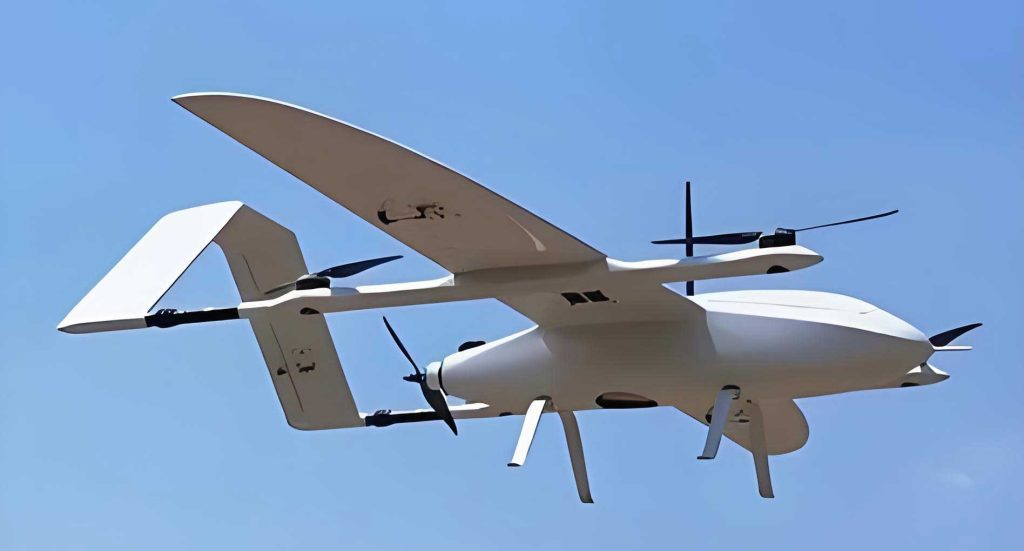
The subject of this study is a compound VTOL drone featuring a conventional fixed-wing airframe integrated with a multirotor system. The primary lifting surface is a wing with a span of 2.4 meters and a constant chord of 0.24 meters. The VTOL capability is provided by four electric rotors. A key feature of this VTOL drone’s design is its multi-mode operation: during vertical take-off, hover, and landing, all four rotors operate with their discs in a horizontal plane to generate vertical thrust. For cruise flight, three rotors are stopped and feathered (or fold), while the fourth rotor, mounted on the tail boom, tilts its disc 90 degrees to act as a tractor propeller, providing forward thrust. This analysis simplifies the system to concentrate on the fundamental interaction by studying a single rotor in proximity to a section of the wing, excluding other airframe components like the fuselage and tail boom.
The core of the investigation revolves around two distinct installation schemes for the rotor relative to the wing, as defined by the distance \(d\) between the rotor disc plane and the wing surface:
- Scheme 1 (Lower Mount): The rotor is installed beneath the wing. In this configuration, during hover, the rotor’s downwash is directed away from the wing’s lower surface.
- Scheme 2 (Upper Mount): The rotor is installed above the wing. Here, the rotor’s downwash impinges directly onto the wing’s upper surface during hover.
In both schemes, the rotor spins to produce an upward lift force. The rotor used is a two-bladed propeller with a diameter of 0.61 meters. The primary goal is to evaluate how the installation scheme and the distance \(d\) affect the hover efficiency of this VTOL drone and its cruise drag.
Computational Methodology and Validation
To analyze the complex, turbulent flow field generated by the rotor and its interaction with the wing, a high-fidelity computational approach was employed. The flow was assumed to be incompressible, valid for the rotor tip speeds involved (Ma < 0.3). The governing equations were solved using a Lattice Boltzmann Method (LBM) coupled with a Wall-Adapting Local Eddy-viscosity (WALE) Large Eddy Simulation (LES) turbulence model. The LBM-LES approach is particularly effective for unsteady, vortex-dominated flows as it naturally handles acoustic and transient phenomena and uses dynamic grid refinement based on local vorticity, providing high accuracy without excessive computational cost. The boundary conditions were set with a velocity inlet and periodic boundaries elsewhere to simulate an unbounded flow domain.
Prior to the interference study, the CFD methodology was rigorously validated against experimental static thrust data for the isolated rotor. The test was conducted on a dedicated rig, measuring thrust at various rotational speeds. The comparison between calculated thrust, theoretical momentum theory estimates, and experimental data is shown in Table 1.
| Rotational Speed (RPM) | Experimental Thrust (N) | CFD Thrust (N) | Momentum Theory Thrust (N) | Deviation (CFD vs Exp.) |
|---|---|---|---|---|
| 2500 | 18.5 | 18.1 | 17.8 | -2.2% |
| 3000 | 27.2 | 26.5 | 26.0 | -2.6% |
| 3500 | 37.8 | 36.9 | 36.5 | -2.4% |
The close agreement between the CFD results and experimental data, with deviations under 3%, confirms the reliability of the chosen numerical model for analyzing the VTOL drone’s components. The slightly higher experimental values are attributed to blockages in the test setup, which the simulation does not replicate.
Hover Performance: Analysis of Installation Schemes
The hover performance of the VTOL drone was evaluated by simulating a static rotor (at 3000 RPM) at various distances \(d\) from the wing for both installation schemes. The key metrics were the isolated rotor thrust \(T_{rotor}\) and the net vertical force of the combined rotor-wing system \(T_{system}\).
The results, summarized graphically and in Table 2, reveal critical insights. For Scheme 1 (Lower Mount), the rotor’s own thrust is minimally affected by the wing, showing only a slight increase at very close distances due to ground-effect-like confinement. The system thrust, however, is significantly lower than the rotor’s isolated thrust because the wing experiences a download force. This download is caused by two main factors: the low-pressure region above the wing created by the rotor’s suction, and the direct impingement of downwash on the wing’s lower surface at close range. As distance \(d\) increases, this interference diminishes. For \(d > 200\) mm, the thrust loss is below 15%.
For Scheme 2 (Upper Mount), the interference is dramatically more severe. The rotor’s downwash strikes the wing’s upper surface, increasing the pressure there and generating a strong download on the wing. This drastically reduces the system’s net thrust. Even at a distance of \(d = 300\) mm, the efficiency loss exceeds 30%, making this scheme highly unfavorable for hover efficiency of the VTOL drone.
| Scheme | Distance \(d\) (mm) | \(T_{rotor}\) (N) | \(T_{system}\) (N) | System Efficiency \(\eta = T_{system}/T_{rotor}\) |
|---|---|---|---|---|
| 1 (Lower) | 50 | 27.8 | 18.5 | 0.665 |
| 150 | 27.1 | 22.8 | 0.841 | |
| 250 | 26.7 | 24.5 | 0.918 | |
| 300 | 26.6 | 25.1 | 0.944 | |
| 2 (Upper) | 50 | 28.1 | 12.1 | 0.431 |
| 150 | 27.3 | 16.9 | 0.619 | |
| 250 | 26.9 | 19.2 | 0.714 | |
| 300 | 26.7 | 20.5 | 0.768 |
The flow field visualizations at \(d = 150\) mm further explain this. In Scheme 1, the wing remains largely outside the high-velocity downwash stream, resulting in a relatively clean low-pressure region on its lower surface. In Scheme 2, the wing is immersed in a high-velocity, high-pressure jet from the rotor, creating massive pressure drag. The power loading (thrust per unit power) for Scheme 1 is consistently and significantly higher than for Scheme 2 across the same disk loading range, conclusively proving the superiority of the lower-mounted configuration for the hover phase of this VTOL drone.
Determining the Optimal Installation Distance
While a larger distance \(d\) in Scheme 1 improves hover efficiency, it also influences the cruise performance of the VTOL drone. A larger protruding rotor mount increases the aerodynamic drag in forward flight. Therefore, the optimal design must balance hover performance against cruise performance based on a specific mission profile.
For this VTOL drone, a typical mission is defined: Hover Time \(T_h = 10\) minutes and Cruise Time \(T_c = 60\) minutes at a speed of \(V = 20\) m/s. The required hover thrust per rotor is \(F_h = 30\) N. The total energy consumption \(E_{total}\) for the mission is the sum of hover energy \(E_h\) and cruise energy \(E_c\).
$$E_{total}(d) = E_h(d) + E_c(d) = \frac{P_h(d) \cdot T_h}{\eta} + \frac{P_c(d) \cdot T_c}{\eta}$$
where \(P_h(d)\) is the power required to generate 30N of system thrust at distance \(d\) (derived from hover simulations), \(P_c(d)\) is the cruise power (a function of drag, which depends on \(d\)), and \(\eta\) represents the combined efficiency of the motor, speed controller, and propeller (assumed 0.8 for this analysis). The cruise drag coefficient \(C_D(d)\) of the airframe with the rotor mount was obtained from CFD simulations in forward flight configuration (rotors stationary). The results are presented in Table 3.
| Distance \(d\) (mm) | Hover Power for 30N \(P_h\) (W) | Cruise Drag Coeff. \(C_D\) | Cruise Power \(P_c\) (W) | Total Mission Energy \(E_{total}\) (kJ) |
|---|---|---|---|---|
| 50 | 285 | 0.0482 | 118 | 648 |
| 100 | 245 | 0.0510 | 125 | 626 |
| 150 | 235 | 0.0538 | 132 | 638 |
| 200 | 228 | 0.0566 | 139 | 654 |
| 250 | 225 | 0.0594 | 146 | 672 |
The data shows a clear trade-off. As \(d\) increases, \(P_h\) decreases (better hover efficiency) but \(P_c\) increases (higher cruise drag). The total mission energy \(E_{total}\) has a distinct minimum at \(d = 100\) mm. This point represents the optimal compromise for the given mission profile, minimizing the overall energy consumption of the VTOL drone.
Conclusion
This comprehensive analysis of rotor-wing interference for a compound VTOL drone yields definitive guidelines for design optimization. The lower mounting scheme (rotor beneath the wing) is conclusively superior to the upper mounting scheme, offering significantly higher hover efficiency due to reduced adverse pressure interactions. For the lower mount configuration, the hover efficiency of the system improves monotonically with increasing distance between the rotor and wing. However, when considering the complete mission profile encompassing both hover and cruise flight, a holistic optimization is required. The analysis identifies an optimal installation distance (in this case, 100 mm) that minimizes the total energy consumption for the specified VTOL drone mission, balancing the gains in hover efficiency against the penalties in cruise drag. These findings provide a critical framework for the aerodynamic integration of lift systems in hybrid VTOL drone platforms.