The evolution of unmanned aerial vehicles (UAVs) has been significantly advanced by the development of hybrid Vertical Take-Off and Landing (VTOL) platforms. These aircraft ingeniously merge the distinct advantages of multi-rotor and fixed-wing configurations. A VTOL drone of this class inherits the multi-rotor’s invaluable ability for hover and vertical take-off/landing, eliminating the need for runways. Simultaneously, it retains the fixed-wing’s superior aerodynamic efficiency, enabling extended endurance and high-speed forward flight. This dual-mode capability dramatically expands operational envelopes, making such platforms exceptionally suitable for a wide array of applications including long-range reconnaissance, infrastructure inspection, rapid delivery, and search-and-rescue missions in complex environments.
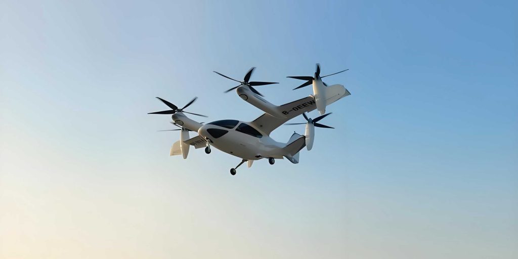
Among various hybrid VTOL configurations, the tail-sitter architecture stands out for its mechanical simplicity and low weight penalty. A tail-sitter VTOL drone does not employ separate rotors for lift and thrust or complex tilting mechanisms. Instead, it takes off and lands on its tail, with its body aligned vertically. For forward flight, it pitches over completely, flying like a conventional fixed-wing aircraft. This elegant solution minimizes “dead weight” but demands that the vehicle operate across an exceptionally wide flight envelope, encompassing hover, transition, and high-speed cruise. This entire envelope is characterized by large, rapid changes in the angle of attack (AoA, $\alpha$) and the resulting highly nonlinear aerodynamic effects. Accurately modeling and controlling these nonlinearities is the principal challenge in unlocking the full potential of the tail-sitter VTOL drone for precise, agile maneuvers.
Traditional control approaches, such as cascaded Proportional-Integral-Derivative (PID) loops, are commonly deployed due to their simplicity. In these schemes, an outer position loop generates acceleration commands, which are then translated into attitude commands for an inner attitude loop. However, this decoupled design faces fundamental limitations. The translation of desired acceleration into a physically feasible attitude command for the VTOL drone is non-trivial, often requiring pre-computed lookup tables or simplified aerodynamic assumptions. More critically, to ensure the stability of the inner attitude loop, the bandwidth of the outer position loop must be severely constrained. This limitation inherently caps trajectory tracking accuracy and agility, especially during dynamic transitions where aerodynamic forces change rapidly.
Nonlinear Model Predictive Control (NMPC) presents a powerful alternative by directly addressing these coupling and constraint-handling challenges. NMPC employs an internal dynamic model of the VTOL drone to predict future states over a finite horizon. It then solves an online optimization problem at each control step to find a sequence of control inputs that minimizes a cost function (e.g., tracking error) while respecting system constraints. This “receding horizon” approach allows NMPC to anticipate and optimally respond to future reference changes and nonlinear dynamics, naturally coordinating position and attitude control in a single optimization. Recent advances in efficient Quadratic Programming (QP) solvers and embedded computing have made real-time NMPC feasible for agile drones.
The performance of NMPC is intrinsically tied to the accuracy of its internal prediction model. For a quadrotor operating at low speeds, a simple rigid-body model may suffice. However, for a high-speed tail-sitter VTOL drone, unmodeled aerodynamic forces (lift, drag, side force, and their corresponding moments) lead to significant prediction errors and degraded tracking. While high-fidelity aerodynamic models can be derived from computational fluid dynamics (CFD) or wind-tunnel data, they are often too complex for real-time optimization, creating a trade-off between model fidelity and computational tractability.
This work proposes a comprehensive solution: a Neural Network Aerodynamic Predictive Model-based NMPC controller for precise, full-envelope trajectory tracking of a tail-sitter VTOL drone. Our key contributions and methodology are as follows:
- Streamlined Aerodynamic NMPC Formulation: We design an NMPC framework that strategically simplifies the aerodynamic model integrated into the prediction. We retain only the most significant nonlinear aerodynamic coefficient (primarily lift/drag along the body’s vertical axis) and rely on the lower-level controller to compensate for less critical forces. Furthermore, by explicitly enforcing a coordinated flight condition within the NMPC cost function, we inherently minimize lateral aerodynamic effects. This focused modeling dramatically reduces optimization complexity, paving the way for real-time implementation.
- Data-Driven Model Identification: We present a practical pipeline for identifying the necessary aerodynamic model without reliance on prior high-fidelity data or costly experiments. An initial “model-free” NMPC controller is used to track a reference trajectory while attempting to maintain coordinated flight. The flight data generated during this process is collected, cleaned, and used to train a Neural Network (NN) to predict the key aerodynamic coefficient as a function of the angle of attack.
- Pareto-Optimal Model Selection: Recognizing the trade-off between model accuracy and computational load, we train a family of NN models with varying complexities. We then evaluate them based on their prediction error on critical flight regimes and their parameter count (a proxy for computational cost). Models on the Pareto front are selected for final controller integration and evaluation.
High-fidelity software-in-the-loop (SITL) simulations demonstrate that our proposed Neural Network Aerodynamic NMPC significantly outperforms both a baseline model-free NMPC and NMPC using other parametric model structures (like truncated Fourier series or linear models). It achieves sub-meter tracking accuracy across the entire flight envelope, including aggressive transitions, while maintaining the computational efficiency required for real-time deployment on actual VTOL drone hardware.
1. System Modeling and Differential Flatness
1.1 Coordinate Frames and Kinematics
We define two primary coordinate frames. The inertial world frame $\mathcal{W}$ is defined by the orthonormal basis $\{\mathbf{e}_x^\mathcal{W}, \mathbf{e}_y^\mathcal{W}, \mathbf{e}_z^\mathcal{W}\}$, with $\mathbf{e}_z^\mathcal{W}$ pointing against gravity. The body frame $\mathcal{B}$ is attached to the VTOL drone at its center of mass, with $\mathbf{e}_x^\mathcal{B}$ pointing forward along the fuselage, $\mathbf{e}_y^\mathcal{B}$ to the right wing, and $\mathbf{e}_z^\mathcal{B}$ completing the right-handed system (downwards when in level flight).
The vehicle’s position, velocity, and acceleration in $\mathcal{W}$ are denoted $\mathbf{p}$, $\mathbf{v}$, and $\mathbf{a}$, respectively. Its attitude is represented by the rotation matrix $\mathbf{R} \in SO(3)$ from $\mathcal{B}$ to $\mathcal{W}$, and its body angular velocity is $\boldsymbol{\Omega}^\mathcal{B} = [p, q, r]^T$. The dynamics of the rigid-body VTOL drone are governed by the Newton-Euler equations:
$$
\begin{aligned}
\dot{\mathbf{p}} &= \mathbf{v} \\
\dot{\mathbf{v}} &= \mathbf{a} = \mathbf{g} + \frac{1}{m} \mathbf{R} (\mathbf{f}_T + \mathbf{f}_a) \\
\dot{\mathbf{R}} &= \mathbf{R} \cdot \text{skew}(\boldsymbol{\Omega}^\mathcal{B}) \\
\mathbf{J} \dot{\boldsymbol{\Omega}}^\mathcal{B} &= \mathbf{M} – \boldsymbol{\Omega}^\mathcal{B} \times \mathbf{J} \boldsymbol{\Omega}^\mathcal{B}
\end{aligned}
$$
Here, $m$ is the mass, $\mathbf{g}=[0,0,-g]^T$ is gravity, $\mathbf{J}$ is the inertia tensor, $\mathbf{f}_T$ and $\mathbf{f}_a$ are the thrust and aerodynamic force vectors in $\mathcal{B}$, and $\mathbf{M}$ is the total moment in $\mathcal{B}$.
1.2 Actuation and Simplified Aerodynamic Force Model
The tail-sitter VTOL drone is actuated by four propellers. The total thrust $\mathbf{f}_T$ is modeled to act along $\mathbf{e}_x^\mathcal{B}$, and the control moment $\mathbf{M}_T$ is generated via differential thrust. The key simplification in our NMPC model concerns the aerodynamic force $\mathbf{f}_a$. A full model would include components along all three body axes as complex functions of AoA ($\alpha$) and sideslip angle ($\beta$):
$$
\mathbf{f}_a = \frac{1}{2} \rho S V^2
\begin{bmatrix}
C_X(\alpha, \beta) \\
C_Y(\alpha, \beta) \\
C_Z(\alpha, \beta)
\end{bmatrix} \equiv m V^2
\begin{bmatrix}
c_x(\alpha, \beta) \\
c_y(\alpha, \beta) \\
c_z(\alpha, \beta)
\end{bmatrix}
$$
where $\rho$ is air density, $S$ is a reference area, $V=||\mathbf{v}||$ is airspeed, and $c_{(\cdot)}$ are normalized aerodynamic coefficients. For a VTOL drone in coordinated flight (i.e., zero sideslip, $\beta \approx 0$), the lateral force $c_y$ is negligible. Furthermore, inspired by Incremental NDI principles, we assume the fast actuator dynamics can compensate for the relatively slower-varying drag force along $\mathbf{e}_x^\mathcal{B}$, represented by $c_x$. Therefore, for the NMPC prediction model, we simplify drastically:
$$
\mathbf{f}_a^{\text{(pred)}} = m V^2
\begin{bmatrix}
0 \\
0 \\
c_z(\alpha)
\end{bmatrix}
$$
This reduces the aerodynamic modeling challenge to identifying a single nonlinear function $c_z(\alpha)$. The unmodeled forces are left for the lower-level incremental controller to reject. This is a critical design choice to keep the NMPC optimization tractable.
1.3 Differential Flatness and Coordinated Flight
The concept of differential flatness is instrumental in generating feasible trajectories and control commands. For the tail-sitter VTOL drone in coordinated flight, the system is differentially flat with the position $\mathbf{p}$ in $\mathcal{W}$ as the flat output. This implies all states and inputs can be expressed as algebraic functions of $\mathbf{p}$ and its derivatives.
Given a sufficiently smooth desired trajectory $\mathbf{p}_{\text{ref}}(t)$, we can compute its derivatives:
$$
\mathbf{v}_{\text{ref}} = \dot{\mathbf{p}}_{\text{ref}}, \quad \mathbf{a}_{\text{ref}} = \ddot{\mathbf{p}}_{\text{ref}}
$$
The desired body $y$-axis direction, which defines the coordinated flight condition (bank-to-turn), is derived from the cross-product of velocity and the specific acceleration excluding gravity:
$$
\mathbf{y}_{\mathcal{B}, \text{ref}} = \text{normalize}\left( \mathbf{v}_{\text{ref}} \times (\mathbf{a}_{\text{ref}} – \mathbf{g}) \right)
$$
If the VTOL drone perfectly tracks the reference trajectory ($\mathbf{v}=\mathbf{v}_{\text{ref}}$, $\mathbf{a}=\mathbf{a}_{\text{ref}}$), then enforcing $\mathbf{y}_{\mathcal{B}} = \mathbf{y}_{\mathcal{B}, \text{ref}}$ ensures coordinated flight, minimizing sideslip. Our NMPC will use $\mathbf{y}_{\mathcal{B}, \text{ref}}$ as a reference to penalize deviations from this ideal condition, effectively regulating $\beta$ to zero without explicitly modeling $c_y$.
2. Neural Network Aerodynamic NMPC Controller Design
2.1 NMPC State, Dynamics, and Neural Network Model
To prevent control input chatter, we augment the state with the thrust vector $\mathbf{f}_T$ and use its derivative $\dot{\mathbf{f}}_T$ as the control input. The augmented state $\mathbf{s}$ and control input $\mathbf{u}$ are:
$$
\mathbf{s} = [\mathbf{p}^T, \mathbf{v}^T, \boldsymbol{\Omega}^{\mathcal{B}^T}, \mathbf{q}^T, \mathbf{f}_T^T]^T, \quad \mathbf{u} = \dot{\mathbf{f}}_T
$$
where $\mathbf{q}$ is the unit quaternion representing attitude. The continuous-time prediction model $\dot{\mathbf{s}} = \mathbf{f}_{\text{pred}}(\mathbf{s}, \mathbf{u})$ is:
$$
\begin{aligned}
\dot{\mathbf{p}} &= \mathbf{v} \\
\dot{\mathbf{v}} &= \mathbf{g} + \frac{1}{m} \mathbf{R}(\mathbf{q}) (\mathbf{f}_T + \mathbf{f}_a^{\text{(pred)}}) \\
\dot{\boldsymbol{\Omega}}^\mathcal{B} &= \mathbf{J}^{-1} (\mathbf{M}_T(\mathbf{f}_T) – \boldsymbol{\Omega}^\mathcal{B} \times \mathbf{J} \boldsymbol{\Omega}^\mathcal{B}) \\
\dot{\mathbf{q}} &= \frac{1}{2} \mathbf{q} \otimes \begin{bmatrix}0 \\ \boldsymbol{\Omega}^\mathcal{B} \end{bmatrix} \\
\dot{\mathbf{f}}_T &= \mathbf{u}
\end{aligned}
$$
with $\mathbf{f}_a^{\text{(pred)}}$ defined as in Eq. (6). The aerodynamic coefficient $c_z$ in this model is provided by a Neural Network:
$$
c_z^{\text{(NN)}} = \text{NN}_{\boldsymbol{\theta}}(\cos\alpha, \sin\alpha)
$$
We parameterize the input using $\cos\alpha$ and $\sin\alpha$ to inherently respect the periodic nature of aerodynamic forces. A simple Multi-Layer Perceptron (MLP) with $\tanh$ activation functions is used to ensure a smooth and differentiable model, which is crucial for gradient-based optimization.
2.2 The Nonlinear Optimization Problem
The NMPC controller solves the following constrained Nonlinear Programming (NLP) problem in a receding horizon fashion at each time step $t_k$:
$$
\begin{aligned}
\min_{\mathbf{S}, \mathbf{U}} \quad & \sum_{i=0}^{N-1} \left( ||\mathbf{p}_i – \mathbf{p}_{\text{ref}, i}||_{\mathbf{Q}_p}^2 + ||\mathbf{v}_i – \mathbf{v}_{\text{ref}, i}||_{\mathbf{Q}_v}^2 + ||\mathbf{y}_{\mathcal{B},i} – \mathbf{y}_{\mathcal{B},\text{ref},i}||_{\mathbf{Q}_y}^2 + ||\boldsymbol{\Omega}^\mathcal{B}_i||_{\mathbf{Q}_\Omega}^2 + ||\mathbf{u}_i||_{\mathbf{R}}^2 \right) \\
\text{s.t.} \quad & \mathbf{s}_0 = \hat{\mathbf{s}}(t_k) \quad \text{(Initial condition)} \\
& \mathbf{s}_{i+1} = \mathbf{f}_{\text{disc}}(\mathbf{s}_i, \mathbf{u}_i), \quad i=0,\ldots,N-1 \quad \text{(Discretized dynamics)} \\
& \boldsymbol{\Omega}_{\text{min}}^\mathcal{B} \preceq \boldsymbol{\Omega}_i^\mathcal{B} \preceq \boldsymbol{\Omega}_{\text{max}}^\mathcal{B} \quad \text{(Angular rate limits)} \\
& \mathbf{f}_{T,\text{min}} \preceq \mathbf{f}_{T,i} \preceq \mathbf{f}_{T,\text{max}} \quad \text{(Thrust limits)} \\
& \mathbf{u}_{\text{min}} \preceq \mathbf{u}_i \preceq \mathbf{u}_{\text{max}} \quad \text{(Thrust rate limits)}
\end{aligned}
$$
Here, $\mathbf{S}=[\mathbf{s}_0, …, \mathbf{s}_N]$ and $\mathbf{U}=[\mathbf{u}_0, …, \mathbf{u}_{N-1}]$ are the sequences of states and controls over the horizon $N$. $\mathbf{f}_{\text{disc}}$ is the discrete-time version of $\mathbf{f}_{\text{pred}}$ obtained via a 4th-order Runge-Kutta integrator. $\mathbf{Q}_p, \mathbf{Q}_v, \mathbf{Q}_y, \mathbf{Q}_\Omega$ are positive definite weight matrices for position, velocity, body-y-axis error, and angular rate penalties, respectively. $\mathbf{R}$ penalizes control effort. The body-y-axis $\mathbf{y}_{\mathcal{B},i}$ is computed from the predicted states $\mathbf{v}_i$ and $\mathbf{a}_i$.
The solution provides an optimal control sequence $\mathbf{U}^*$. The first control input $\mathbf{u}_0^*$ is integrated to get the thrust command $\mathbf{f}_T^*$, and the first predicted angular rate $\boldsymbol{\Omega}_0^{\mathcal{B}*}$ is used as the angular rate command for the lower-level controller.
2.3 Real-Time Optimization and Lower-Level Control
The NLP is solved using a real-time iteration scheme based on Sequential Quadratic Programming (SQP). The dynamics and cost are linearized at each SQP iteration, forming a Quadratic Program (QP) solved efficiently by the HPIPM solver. The framework is implemented using acados and CasADi, enabling C-code generation for fast execution.
The lower-level controller tracks the NMPC commands. It consists of:
- Angular Rate Controller: A PID controller tracks $\boldsymbol{\Omega}^{\mathcal{B}*}$, generating moment commands $\boldsymbol{\tau}_c$.
- Translational Controller: An incremental integral controller tracks the specific force command implied by $\mathbf{f}_T^*$. It computes a throttle command $\delta_t$ based on the error between the commanded and estimated specific force along $\mathbf{e}_x^\mathcal{B}$.
The commands $\boldsymbol{\tau}_c$ and $\delta_t$ are sent to a mixer that computes individual motor commands for the VTOL drone.
3. Data Collection and Neural Network Aerodynamic Model Identification
3.1 Initial Data Generation with Model-Free NMPC
To collect data for training the NN aerodynamic model $c_z(\alpha)$, we first employ a “model-free” NMPC. This controller uses the same structure as in Section 2.2 but with a drastically simplified prediction model that completely neglects aerodynamics: $\dot{\mathbf{v}} = \mathbf{g} + \frac{1}{m} \mathbf{R}\mathbf{f}_T$. Despite its inaccuracy, this controller can track moderately aggressive trajectories (like a coordinated circular path) while attempting to maintain the coordinated flight condition via the $\mathbf{y}_{\mathcal{B}}$ penalty.
During these flights, we log estimates of the vehicle’s state: position $\hat{\mathbf{p}}$, velocity $\hat{\mathbf{v}}$, attitude $\hat{\mathbf{R}}$, and specifically, the acceleration $\hat{\mathbf{a}}$. The “measured” aerodynamic coefficient $\hat{c}_z$ is then estimated from the accelerometer data using force balance:
$$
\hat{\mathbf{a}} = \mathbf{g} + \frac{1}{m} \hat{\mathbf{R}} (\hat{\mathbf{f}}_T + \hat{\mathbf{f}}_a)
$$
Assuming the estimated thrust $\hat{\mathbf{f}}_T$ is known from the motor model and controller commands, and that the lateral aerodynamic force is small ($\hat{c}_y \approx 0$), we can isolate the vertical component:
$$
\hat{c}_z \approx \frac{ [\hat{\mathbf{R}}^T( m\hat{\mathbf{a}} – m\mathbf{g} ) – \hat{\mathbf{f}}_T ]_z }{ m \hat{V}^2 }
$$
where $[\cdot]_z$ denotes the $\mathbf{e}_z^\mathcal{B}$ component and $\hat{V}=||\hat{\mathbf{v}}||$. The corresponding angle of attack is computed as $\hat{\alpha} = \text{atan2}(\hat{w}, \hat{u})$, where $\hat{u}, \hat{w}$ are the $\mathbf{e}_x^\mathcal{B}$ and $\mathbf{e}_z^\mathcal{B}$ components of the estimated airspeed $\hat{\mathbf{R}}^T\hat{\mathbf{v}}$.
3.2 Data Cleaning and Augmentation
The raw data $\{(\hat{\alpha}_k, \hat{c}_{z,k})\}$ is noisy and contains periods where the coordinated flight assumption is violated (e.g., during large transients). We apply filters:
- Remove uncoordinated flight data: Discard samples where the estimated lateral specific force $|\hat{a}_y|$ exceeds a threshold.
- Remove low-speed data: Discard samples where $\hat{V}$ is below a threshold, as the aerodynamic model is ill-conditioned and propeller wash interference is high.
The resulting dataset covers primarily the cruise and transition AoA range. To inform the model about the high-AoA and negative-AoA regimes (e.g., during vertical hover or rapid pitch-ups), we augment the dataset with synthetic data based on a simple flat-plate drag model, ensuring the NN learns a physically plausible trend across the entire possible $\alpha$ domain.
3.3 Neural Network Training and Pareto Selection
We train a family of MLP models with varying depths (number of layers) and widths (neurons per layer). The loss function is a combination of Mean Squared Error (MSE) on the training data and an L2 regularization term:
$$
\mathcal{L}(\boldsymbol{\theta}) = \frac{1}{N} \sum_{k=1}^{N} ( \text{NN}_{\boldsymbol{\theta}}(\cos\hat{\alpha}_k, \sin\hat{\alpha}_k) – \hat{c}_{z,k} )^2 + \lambda ||\boldsymbol{\theta}||_2^2
$$
After training, we evaluate each model on two key metrics for the critical flight regime (e.g., $\alpha \in [0^\circ, 50^\circ]$):
- Max Absolute Error (MAE): Represents model fidelity in the most important AoA range.
- Parameter Count: Serves as a proxy for the computational cost of evaluating the model within the NMPC’s real-time optimization loop.
We plot these metrics for all trained models and identify the Pareto front—the set of models where improving one metric necessarily worsens the other. Models on this front offer the best trade-offs. For example, a model labeled $\text{NN}_{2,1}$ (2 neurons per layer, 1 hidden layer) might have 9 parameters and low MAE, making it an excellent candidate for real-time control of the VTOL drone.
4. Simulation Results and Performance Evaluation
4.1 Simulation Setup and Comparative Baselines
We validate our framework in a high-fidelity Software-in-the-Loop (SITL) simulation. The VTOL drone dynamics, including a high-fidelity aerodynamic lookup table based on prior work, are simulated in Gazebo. The NMPC controller, state estimator, and lower-level PX4-based controller run in separate ROS2 nodes, mimicking a real hardware setup. The reference trajectory is a 3D lemniscate (figure-eight) with aggressive climb, dive, and high-speed turning segments, challenging the controller across the flight envelope.
We compare the following controllers:
- Baseline (BL): Model-free NMPC (no $c_z$ model).
- Lin-Aero: NMPC with a simple linear model $c_z(\alpha) = c_{z0} + c_{z\alpha} \alpha$ fitted to low-AoA data.
- TFS-9: NMPC with a 9-parameter Truncated Fourier Series model $c_z(\alpha)=a_0 + \sum_{k=1}^4 (a_k \cos(k\alpha) + b_k \sin(k\alpha))$.
- Proposed NN_{2,1}: Our NMPC with the Pareto-optimal neural network model (2×1 structure).
4.2 Tracking Performance Analysis
The tracking performance is quantified using Root Mean Square Error (RMSE) and Maximum Error over multiple simulation runs. The results clearly demonstrate the advantage of the learned neural network model.
| Controller | Horiz. RMSE [m] | Vert. RMSE [m] | Max Pos. Error [m] | Avg. NMPC Solve Time [ms] |
|---|---|---|---|---|
| Baseline (BL) | 2.65 | 4.71 | 6.92 | 0.65 |
| Lin-Aero | 0.35 | 0.21 | 1.09 | 0.68 |
| TFS-9 | 0.30 | 0.17 | 0.96 | 0.72 |
| Proposed NN_{2,1} | 0.25 | 0.13 | 0.77 | 0.71 |
The proposed NN_{2,1} controller achieves the best tracking accuracy across all metrics, reducing horizontal RMSE by over 90% compared to the baseline. Critically, it maintains a low and consistent solve time (~0.71 ms), well within the typical 20 ms control period for a 50 Hz update rate, proving its real-time feasibility. The Lin-Aero model fails during high-AoA maneuvers where its linear assumption breaks down, leading to larger errors. The TFS-9 model, while better than Lin-Aero, can produce oscillatory predictions due to Gibbs phenomena, sometimes causing jittery control commands.
4.3 Analysis of Aerodynamic Prediction and Control Commands
The effectiveness of the neural network model is visualized by plotting the predicted $c_z^{\text{(NN)}}$ against the true simulation $c_z$ during a flight. The NN model closely matches the true nonlinear profile, especially in the crucial $0^\circ$ to $50^\circ$ AoA range for forward flight and pull-up maneuvers. In contrast, the linear model diverges significantly at higher AoA, and the Fourier series shows small but non-physical wiggles.
Examining the commanded angular rates reveals why tracking improves. During a high-G turn and pull-up, the Baseline NMPC, lacking aerodynamic prediction, commands insufficient pitch rate ($q$) to account for the loss of lift as the VTOL drone bleeds speed and AoA increases. The NN_{2,1} NMPC, anticipating this aerodynamic change through its accurate model, commands a stronger and more timely pitch-up maneuver, allowing the aircraft to track the desired climb trajectory more accurately without stalling.
5. Conclusion and Future Work
This paper presented a novel, practical framework for high-precision trajectory tracking control of a tail-sitter VTOL drone across its entire flight envelope. The core of the solution is a Nonlinear Model Predictive Controller augmented with a data-driven Neural Network aerodynamic model. The main contributions are threefold:
- We designed an NMPC formulation that strategically simplifies the onboard aerodynamic model to a single nonlinear coefficient, explicitly enforces coordinated flight to minimize lateral effects, and uses thrust rate constraints to ensure dynamic feasibility—all contributing to a tractable real-time optimization problem.
- We developed a complete pipeline for identifying the necessary aerodynamic model without prior high-fidelity data. This involves using a suboptimal but stable model-free NMPC to collect flight data, followed by training and selecting a Pareto-optimal neural network model that balances accuracy and computational cost.
- Through comprehensive SITL simulations, we demonstrated that our proposed Neural Network Aerodynamic NMPC significantly outperforms baseline and other parametric model-based controllers. It achieves sub-meter tracking accuracy during aggressive 3D maneuvers while maintaining an average solve time under 1 ms, confirming its suitability for real-time deployment on actual VTOL drone hardware.
The proposed method offers a general and transferable solution for controlling hybrid VTOL aircraft where accurate, simple aerodynamic models are unavailable. Future work will focus on (i) enhancing the framework’s robustness to wind disturbances by incorporating online adaptation of the neural network model or disturbance estimation, and (ii) integrating the controller with a real-time trajectory planner capable of generating dynamically feasible and perception-aware paths for fully autonomous navigation in complex environments.