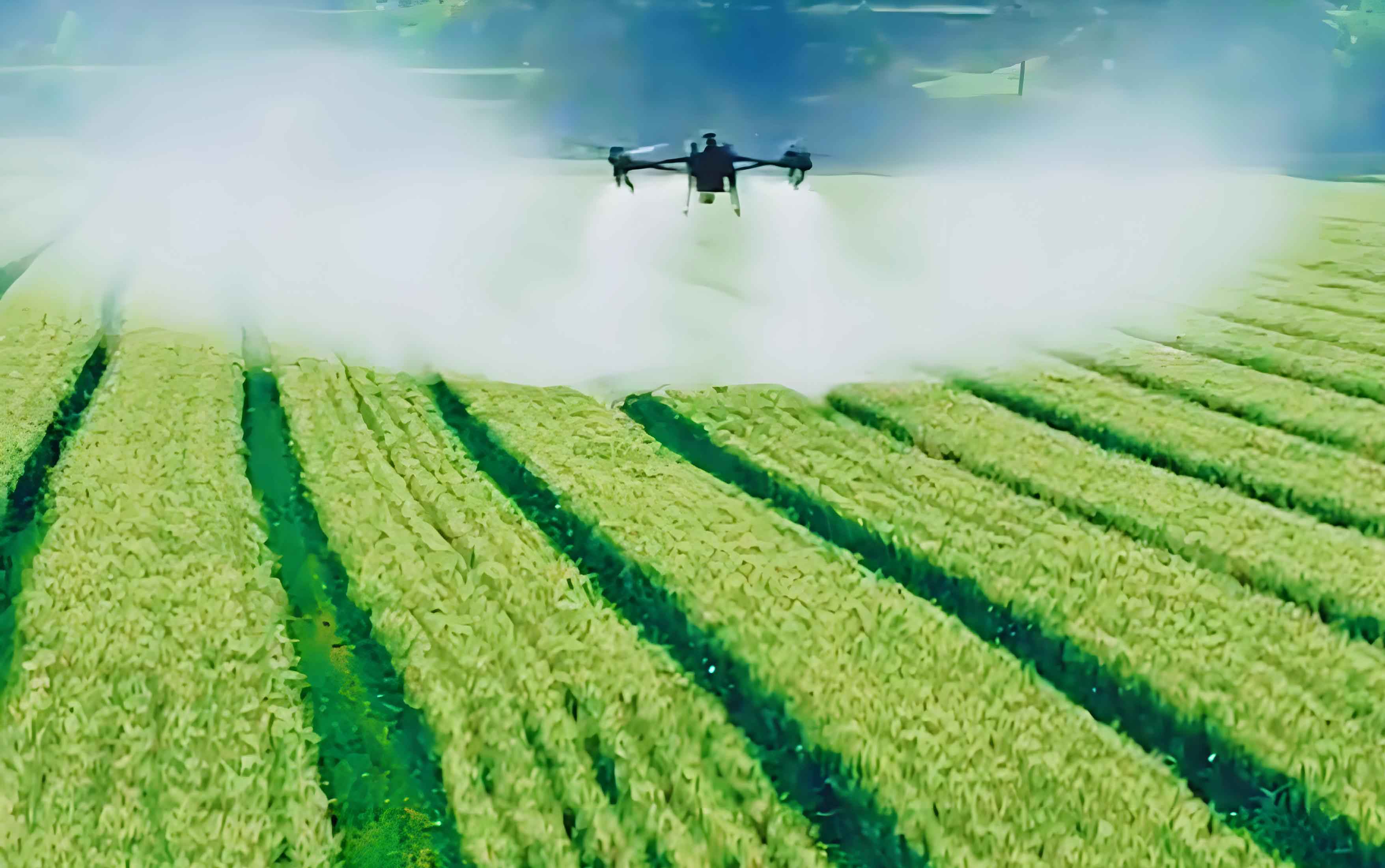
In modern agriculture, the use of crop spraying drones has revolutionized the way we approach tasks such as pesticide and fertilizer application. These spraying UAVs offer significant advantages in terms of efficiency, precision, and reduced labor costs. However, single drone operations often fall short when dealing with large-scale farms, where multiple obstacles like trees, towers, and buildings can impede coverage. To address this, we propose a cooperative operation method for multiple crop spraying drones, forming a coordinated fleet to enhance spraying efficiency and ensure comprehensive coverage. This article presents an improved artificial potential field algorithm for path planning and a sliding mode control strategy for accurate path tracking, enabling a group of spraying UAVs to work synergistically while avoiding obstacles. Our approach not only speeds up the spraying process but also minimizes issues like over-spraying and missed areas, contributing to sustainable and intelligent agriculture.
The core of our method lies in integrating advanced path planning with robust control mechanisms. We begin by establishing mathematical and formation models for the crop spraying drones, accounting for real-world disturbances such as mass changes during spraying. The improved artificial potential field method introduces a loop force to overcome local minima problems, ensuring smooth and obstacle-free paths. Subsequently, we design sliding mode control laws for both the motion and attitude loops of the spraying UAVs, guaranteeing precise tracking of the planned paths. Through extensive simulations and field tests, we demonstrate that our approach outperforms existing methods in terms of path smoothness, tracking accuracy, and operational efficiency. This work paves the way for scalable, autonomous farming solutions using fleets of crop spraying drones.
To model the dynamics of a crop spraying drone, we consider a multi-rotor UAV equipped with a spraying system. The motion model describes the translational dynamics, while the attitude model captures the rotational behavior. For a single spraying UAV, the motion model is given by:
$$ \dot{p} = v $$
$$ \dot{v} = -G + hT + d_v $$
where \( p = [x, y, z]^T \) represents the position vector in meters, \( v = [v_x, v_y, v_z]^T \) is the velocity vector in meters per second, \( G = [g_x, g_y, g_z]^T \) denotes the gravitational acceleration vector in meters per second squared, and \( T = [T_x, T_y, T_z]^T \) is the thrust vector in Newtons. The matrix \( h \) is defined as:
$$ h = \frac{1}{m} \begin{bmatrix} 0 & 0 & \sin \theta \cos \psi \cos \phi + \sin \psi \sin \phi \\ 0 & 0 & \sin \theta \sin \psi \cos \phi – \cos \psi \sin \phi \\ 0 & 0 & \cos \theta \cos \phi \end{bmatrix} $$
Here, \( m \) is the mass of the crop spraying drone in kilograms, and \( \phi \), \( \theta \), and \( \psi \) are the roll, pitch, and yaw angles in degrees, respectively. The term \( d_v \) accounts for disturbances in the motion model, such as wind gusts or mass variations due to spraying fluid depletion.
The attitude model for the spraying UAV is expressed as:
$$ \dot{\Theta} = W \omega $$
$$ \dot{\omega} = f + \Gamma + d_\omega $$
where \( \Theta = [\phi, \theta, \psi]^T \) is the attitude angle vector, \( \omega = [p, q, r]^T \) represents the angular velocity vector in degrees per second, and \( \Gamma = [\Gamma_x, \Gamma_y, \Gamma_z]^T \) is the torque vector in Newton-meters. The matrix \( W \) is given by:
$$ W = \begin{bmatrix} 1 & \sin \phi \tan \theta & \cos \phi \tan \theta \\ 0 & \cos \phi & -\sin \phi \\ 0 & \sin \phi \cos \theta & \cos \phi \cos \theta \end{bmatrix} $$
and \( f = J^{-1} (-\omega \times J \omega) \), with \( J = \text{diag}\{J_x, J_y, J_z\} \) being the inertia matrix. The disturbance term \( d_\omega \) models uncertainties in the attitude dynamics. These equations form the basis for designing control strategies for the crop spraying drones.
For cooperative operations, we organize multiple spraying UAVs into a formation. The leader-follower model is employed, where one drone acts as the leader, and the others follow at predetermined offsets. Let \( \text{UAV}_l \) denote the leader with position \( (x_l, y_l, z_l) \), and \( \text{UAV}_f \) represent a follower with position \( (x_f, y_f, z_f) \). The desired relative position is \( (x_d, y_d, z_d) \), and the formation model is:
$$ x_f = x_l – 2x_c $$
$$ y_f = y_l – 2y_c $$
$$ z_f = z_l – 2z_c $$
Here, \( x_c \) and \( y_c \) are the components of the maximum spraying radius at height \( z_c \). This ensures that the follower crop spraying drones maintain optimal spacing for uniform coverage without overlap. The formation allows the fleet of spraying UAVs to cover large areas efficiently while adapting to obstacles.
Path planning is critical for navigating crop spraying drones through complex environments. We enhance the traditional artificial potential field method by introducing a loop force to resolve local minima issues, where drones might get stuck in repetitive cycles. The total potential field comprises repulsive forces from obstacles and attractive forces toward the goal. The repulsive potential function for an obstacle is defined as:
$$ U_{po}(X_p, X_o) = \begin{cases} +\infty & \text{if } 0 \leq l(X_p, X_o) < R_0 \\ b \left[ \left( \frac{l(X_p, X_o)}{\rho_0} \right)^2 – 2 \ln \left( \frac{l(X_p, X_o)}{\rho_0} \right) – 1 \right] & \text{if } R_0 \leq l(X_p, X_o) \leq R_0 + \rho_0 \\ 0 & \text{if } l(X_p, X_o) > R_0 + \rho_0 \end{cases} $$
where \( l(X_p, X_o) \) is the distance between the drone position \( X_p \) and the obstacle center \( X_o \) in meters, \( R_0 \) is the obstacle radius in meters, \( \rho_0 \) is the radius of the repulsive field in meters, and \( b \) is a gain coefficient. The repulsive force is the negative gradient:
$$ F_{po}(X_p, X_o) = \begin{cases} +\infty & \text{if } 0 \leq l(X_p, X_o) < R_0 \\ b \left( \frac{1}{\rho_0} – \frac{1}{l(X_p, X_o)} \right) & \text{if } R_0 \leq l(X_p, X_o) \leq R_0 + \rho_0 \\ 0 & \text{if } l(X_p, X_o) > R_0 + \rho_0 \end{cases} $$
The attractive potential function toward the target is:
$$ U_{pt}(X_p, X_t) = \begin{cases} -a_1 l^2(X_p, X_t) & \text{if } 0 \leq l(X_p, X_t) < R_p \\ -a_2 l^2(X_p, X_t) & \text{if } l(X_p, X_t) \geq R_p \end{cases} $$
where \( l(X_p, X_t) \) is the distance to the target, \( R_p \) is the formation radius in meters, and \( a_1 \), \( a_2 \) are gain coefficients. The attractive force is:
$$ F_{pt}(X_p, X_t) = \begin{cases} a_1 l(X_p, X_t) & \text{if } 0 \leq l(X_p, X_t) < R_p \\ a_2 l(X_p, X_t) & \text{if } l(X_p, X_t) \geq R_p \end{cases} $$
To address local minima, we introduce a loop force \( F_{pot} \):
$$ F_{pot}(X_p, X_o, X_t) = \begin{cases} \mu \frac{\| F_p(X_p, X_o, X_t) \cdot F_{pt}(X_p, X_t) \|}{\| F_{pt}(X_p, X_t) \|} \cdot \frac{F_{po}(X_p, X_o) \cdot F_{pt}(X_p, X_t) \cdot F_p(X_p, X_o, X_t)}{\| F_{po}(X_p, X_o) \cdot F_{pt}(X_p, X_t) \cdot F_p(X_p, X_o, X_t) \|} & \text{if } 0 \leq l(X_p, X_o) < R_0 + \rho_0 \\ 0 & \text{otherwise} \end{cases} $$
where \( F_p = F_{pt} + F_{po} \), and \( \mu \) is a tuning parameter. The total force acting on the crop spraying drone is:
$$ F(X_p, X_o, X_t) = F_{pt}(X_p, X_t) + F_{po}(X_p, X_o) + F_{pot}(X_p, X_o, X_t) $$
From this, the velocity of the spraying UAV is derived as \( v_p = \frac{F(X_p, X_o, X_t)}{m_p} \delta \), where \( m_p \) is the formation mass in kilograms, and \( \delta \) is the step size. The heading and pitch angles are computed as:
$$ \psi_p = \arctan \left( \frac{F_y}{F_x} \right) $$
$$ \theta_p = \arctan \left( \frac{F_z}{\sqrt{F_x^2 + F_y^2}} \right) $$
where \( F_x \), \( F_y \), and \( F_z \) are the components of the total force. The leader’s path is then generated by integrating the velocity components over time.
For precise path tracking, we design sliding mode control laws for the motion and attitude loops of the crop spraying drones. This ensures robustness against disturbances and model uncertainties. Define the path tracking error for the motion loop as \( e_1 = p – p_d \), where \( p_d \) is the desired path from the improved artificial potential field method. Let \( e_2 = v + c_1 e_1 – \dot{p}_d \), with \( c_1 > 0 \) being a control parameter. The sliding surface is:
$$ S_1 = k_1 e_1 + e_2 = (k_1 + c_1) e_1 + \dot{e}_1 $$
where \( k_1 > 0 \). Consider the Lyapunov function \( V_1 = \frac{1}{2} e_1^T e_1 + \frac{1}{2} S_1^T S_1 \). Its derivative is:
$$ \dot{V}_1 = e_1^T (v – \dot{p}_d) + S_1^T \left[ (k_1 + c_1) \dot{e}_1 + \ddot{e}_1 \right] $$
Substituting the motion model and simplifying, we derive the control law for thrust:
$$ T = h^{-1} \left[ G – (k_1 + c_1) \dot{e}_1 + \ddot{p}_d – k_2 S_1 – \text{sgn}(S_1) – (S_1^T)^{-1} e_1^T e_2 – D_v \text{sgn}(S_1) \right] $$
where \( k_2 > 0 \), \( D_v \) is the upper bound of \( d_v \), and \( \text{sgn}(\cdot) \) is the sign function. This ensures \( \dot{V}_1 \leq -c_1 e_1^T e_1 – k_2 S_1^T S_1 – \| S_1^T \| \leq 0 \), guaranteeing stability. The attitude commands are computed from \( T \) as:
$$ \psi_d = \arctan \left( \frac{y_d}{x_d} \right) $$
$$ \phi_d = \arcsin \left( \frac{T_x \sin \psi – T_y \cos \psi}{\sqrt{T_x^2 + T_y^2 + T_z^2}} \right) $$
$$ \theta_d = \arctan \left( \frac{T_x \cos \psi + T_y \sin \psi}{T_z + m g} \right) $$
For the attitude loop, define the tracking error \( e_3 = \Theta – \Theta_d \), and let \( e_4 = W \omega + c_2 e_3 – \dot{\Theta}_d \), with \( c_2 > 0 \). The sliding surface is:
$$ S_2 = k_3 e_3 + e_4 = (k_3 + c_2) e_3 + \dot{e}_3 $$
where \( k_3 > 0 \). Using the Lyapunov function \( V_2 = \frac{1}{2} e_3^T e_3 + \frac{1}{2} S_2^T S_2 \), the derivative is:
$$ \dot{V}_2 = e_3^T (W \omega – \dot{\Theta}_d) + S_2^T \left[ (k_3 + c_2) \dot{e}_3 + \ddot{e}_3 \right] $$
The control law for torque is:
$$ \Gamma = W^{-1} \left[ -W f – (k_3 + c_2) \dot{e}_3 + \ddot{\Theta}_d – k_4 S_2 – \text{sgn}(S_2) – (S_2^T)^{-1} e_3^T e_4 – W D_\omega \text{sgn}(S_2) \right] $$
where \( k_4 > 0 \) and \( D_\omega \) is the upper bound of \( d_\omega \). This ensures \( \dot{V}_2 \leq -c_2 e_3^T e_3 – k_4 S_2^T S_2 – \| S_2^T \| \leq 0 \), maintaining stability in the attitude loop.
To validate our approach, we conducted simulations with a fleet of five crop spraying drones operating in a 90 m × 150 m area containing obstacles such as trees and towers. The parameters for the improved artificial potential field method and sliding mode control were tuned for optimal performance. The table below summarizes key simulation parameters:
| Parameter | Value | Description |
|---|---|---|
| Formation Size | 5 drones | Number of spraying UAVs |
| Area Dimensions | 90 m × 150 m | Spraying region |
| Obstacle 1 (Tree) | Center (20, 3), R₀ = 3 m | Radius and position |
| Obstacle 2 (Water Tower) | Center (60, 57), R₀ = 7.5 m | Radius and position |
| Obstacle 3 (Pylon) | Center (120, 85), R₀ = 5 m | Radius and position |
| Repulsive Field Radius (ρ₀) | 0.5 m | Influence range of obstacles |
| Formation Radius (R_p) | 15 m | Spacing between spraying UAVs |
| Control Parameters (c₁, k₁, k₂, c₂, k₃, k₄) | 8, 6, 10, 9, 5, 12 | Tuned for stability |
The improved artificial potential field method generated smooth, obstacle-free paths in approximately 1.2 seconds, significantly faster than traditional methods like A* algorithm, which produced jagged paths and took over 2.1 seconds. The sliding mode control ensured accurate path tracking, with a maximum deviation error of only 0.12 meters, compared to 1.89 meters for adaptive control methods. This highlights the superiority of our approach for crop spraying drones in dynamic environments.
Field tests were conducted using five crop spraying drones (model: HaoYing X9 Plus) on a wheat field of the same dimensions, with obstacles like utility poles. We compared our method against a combination of improved A* path planning and adaptive control (IA-ADAT). The results, summarized in the table below, demonstrate the effectiveness of our approach in real-world conditions:
| Metric | IA-ADAT Method | Our Method |
|---|---|---|
| Max Trajectory Deviation (m) | 1.55 | 0.21 |
| Over-Sprayed Area (m²) | 236.3 | 41.6 |
| Over-Sprayed Percentage (%) | 1.75 | 0.31 |
| Missed Area (m²) | 252.4 | 45.7 |
| Missed Percentage (%) | 1.87 | 0.34 |
| Operation Time (s) | 251 | 239 |
Our method reduced over-spraying and missed areas by over 80%, while also shortening the operation time, proving its efficiency for large-scale farming with spraying UAVs. The integration of improved path planning and robust control allows crop spraying drones to achieve near-perfect coverage, even in obstructed terrains.
In conclusion, we have developed a comprehensive framework for cooperative path planning and control of crop spraying drones. The improved artificial potential field method efficiently generates smooth, obstacle-avoiding paths, and the sliding mode control ensures precise tracking under disturbances. This approach significantly enhances the performance of spraying UAV fleets, reducing operational time and minimizing resource waste. Future work will focus on incorporating real-time environmental perception for moving obstacles and adaptive formation reconfiguration, further advancing the autonomy of crop spraying drones in intelligent agriculture.