In recent years, the rapid growth of e-commerce has highlighted the critical importance of the “last mile” delivery in logistics. Compared to manual delivery, multirotor drone delivery offers advantages such as small size, low cost, rapid deployment, and simple operation, significantly reducing logistical pressures. Moreover, in the context of the COVID-19 pandemic, minimizing unnecessary human contact has become a norm, further accelerating the adoption of multirotor drones in logistics. However, traditional multirotor drones face limitations in payload capacity, endurance, and adaptability to diverse cargo types. This paper addresses these challenges by designing an improved logistics multirotor drone based on Arduino, featuring a claw-type pickup mechanism, retractable landing gear, and hollowed internal structures to reduce weight and enhance endurance. The drone utilizes a high-capacity lithium battery and a solar panel for auxiliary power, with performance validated through SolidWorks Simulation.
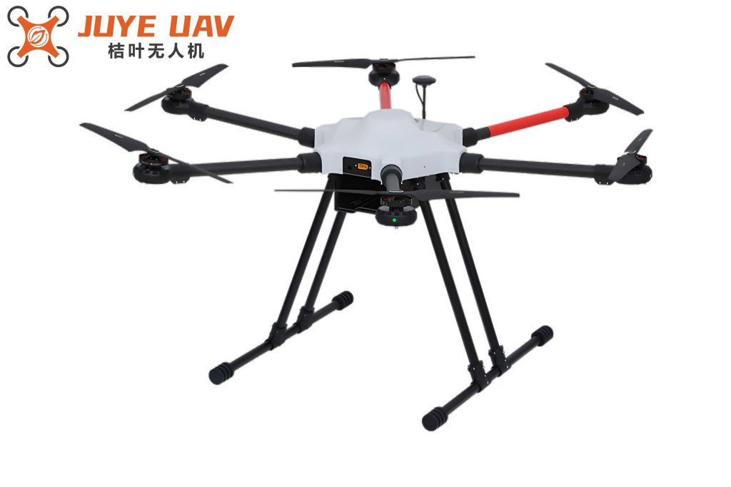
The overall design of the logistics multirotor drone focuses on optimizing endurance, payload capacity, and automation. Key improvements include a claw-type pickup system for automated loading and unloading, retractable landing gear to reduce air resistance during flight, and hollowed structures in non-critical areas to minimize weight. The drone’s frame is constructed from carbon fiber and PLA materials, combining strength with lightness. A solar panel mounted on the top shell provides auxiliary charging, while a large-capacity lithium battery ensures extended operation. The multirotor drone is controlled by an Arduino development board and a flight controller, enabling precise execution of tasks such as takeoff, hovering, and landing. The basic flight mission profile involves vertical ascent with retracted landing gear, hover at designated positions, and controlled descent with extended landing gear for safe payload delivery.
The multirotor drone’s layout is symmetric, with arms and landing gear evenly distributed to maintain stability. To counteract gyroscopic effects, the drone employs counter-rotating motors and propellers. The frame consists of an upper shell housing the GPS and solar panel, a middle plate with a power distribution board, receiver, and ESCs, and a lower shell containing the battery and flight controller. The claw mechanism, integrated into the lower shell, uses a worm gear system for self-locking and precise grip, capable of handling items up to 5 kg. Parameters such as frame span, diameter, height, and mass are summarized in Table 1.
| Parameter | Value |
|---|---|
| Frame Span (mm) | 680 |
| Overall Diameter (mm) | 1070 |
| Overall Height (mm) | 340 |
| Self Mass (g) | 2000 |
| Claw Mass (g) | 600 |
| Claw Grip Force (N) | 25 |
The retractable landing gear design reduces air resistance during ascent and descent. It consists of landing gear, servos, and a four-bar linkage mechanism. Commands sent from a mobile device to the Arduino board control servo rotation, lifting or lowering the landing gear by 60 degrees. This ensures smooth operation without jamming. The solar panel, a polycrystalline silicon drip-coated board, converts solar energy to electricity, supplementing the battery and improving the multirotor drone’s endurance. The claw mechanism, equipped with a camera, allows visual confirmation of pickup and drop-off points, enhancing automation.
The control system integrates an Arduino board and a flight controller. The Arduino manages the landing gear and claw operations, while the flight controller handles flight dynamics, including takeoff, hovering, and landing. Commands from a mobile interface trigger servo movements for gear retraction and claw actuation. The flight controller adjusts motor speeds for stability and precision, especially during descent and payload handling. The control system workflow ensures coordinated operation of all modules, as illustrated in the following diagram.
Component selection is critical for performance. The multirotor drone uses TYI-5008 KV400 brushless motors, each providing a thrust of 1.92 kg, with 1655 carbon fiber propellers. The motors are powered by a Li-241000 lithium battery with a capacity of 10 Ah, outputting 25.2–18 V at 5 A. The solar panel aids in charging, extending flight time. Motor thrust must satisfy the condition for stable flight, calculated as the total thrust exceeding 1.5 times the drone’s weight. The maximum payload is 2.5 kg, with a total mass of 5.1 kg, requiring a minimum thrust of 7.65 kg. Thus, each motor must provide at least 1.9125 kg of thrust, met by the selected motors. The battery endurance is derived from the formula:
$$ \text{Endurance} = \frac{\text{Battery Capacity} \times 60}{\text{Total Current Draw}} $$
Assuming a 70% throttle under adverse conditions, the current draw per motor is 6.09 A, resulting in a total draw of 24.36 A. With a 10 Ah battery, the endurance is approximately 24.6 minutes, extendable to 27 minutes with solar assistance. Key motor and battery parameters are listed in Tables 2 and 3.
| Parameter | Value |
|---|---|
| Model | TYI-5008 KV400 |
| Voltage (V) | 24 |
| Propeller | 1655 Carbon Fiber |
| Throttle (%) | 60 |
| Current (A) | 8.7 |
| Power (W) | 208.8 |
| Mass (g) | 156 |
| Load (kg) | 1.92 |
| Parameter | Value |
|---|---|
| Model | Li-241000 |
| Dimensions (mm) | 85 × 28 × 145 |
| Input Voltage (V) | 25 |
| Capacity (Ah) | 10 |
| Mass (g) | 620 |
| Output Voltage (V) | 25.2–18 |
| Max Current (A) | 10 |
| Cycle Life | ~1000 |
| Operating Temperature (°C) | -10 to 50 |
Structural integrity is verified using SolidWorks Simulation. The middle plate, made of carbon fiber, is analyzed under a 500 N load applied from above. The simulation evaluates stress, displacement, and strain. The maximum stress occurs at the edges of hollowed sections, with a value of \(2.680 \times 10^4\) Pa, well below the material’s yield strength. Displacement is minimal, peaking at \(1.177 \times 10^{-4}\) mm at the outer edges, while strain reaches \(8.821 \times 10^{-6}\) mm in hollowed areas. These results confirm the design’s reliability under operational loads. The stress distribution is given by:
$$ \sigma = \frac{F}{A} $$
where \( \sigma \) is stress, \( F \) is force, and \( A \) is area. The low values ensure safety. Displacement \( \delta \) and strain \( \epsilon \) are derived from:
$$ \delta = \frac{FL}{AE}, \quad \epsilon = \frac{\delta}{L} $$
with \( E \) as the modulus of elasticity. The multirotor drone’s design meets all structural requirements.
In conclusion, this logistics multirotor drone design effectively addresses endurance and payload challenges through innovative features like retractable landing gear, a claw mechanism, and solar-assisted power. The use of Arduino and flight control systems ensures precise automation, while material selection and structural optimization enhance performance. The multirotor drone is suitable for various logistics applications, offering a sustainable and efficient solution for last-mile delivery. Future work could focus on scaling the design for heavier payloads and integrating advanced navigation systems.