Transmission lines are critical components of power systems, responsible for the transmission and distribution of electricity, and their stable operation is essential for overall system reliability. However, due to long-term exposure to outdoor environments, transmission lines are susceptible to environmental influences that can lead to faults, potentially disrupting the entire power system. Therefore, it is necessary to conduct regular inspections of transmission lines. In recent years, with the advancement of Unmanned Aerial Vehicle technology, drone-based inspection methods have gradually replaced traditional manual approaches, not only improving inspection speed and reducing labor costs but also better adapting to complex outdoor environments, thus meeting the demands of power inspections more effectively. This paper focuses on a quadrotor Unmanned Aerial Vehicle as the research object, proposing a tracking control method for transmission line inspection based on drone technology. The control objective is to enable the drone to track a desired trajectory within a limited time under speed constraints, achieved by designing a finite-time position controller. This approach allows the drone to perform inspection tracking along transmission lines, enhancing inspection efficiency and accuracy.
The application of drone technology in transmission line inspection has shown significant promise, as it enables autonomous navigation and real-time data collection. For instance, previous studies have integrated 5G connectivity and LiDAR sensors with Unmanned Aerial Vehicles to achieve intelligent inspection capabilities, such as defect detection and fault analysis. However, challenges remain in improving tracking control performance, particularly under speed limitations and environmental disturbances. Our work addresses this by developing a robust controller that ensures precise trajectory tracking, even in the presence of obstacles or foreign objects on the lines. The proposed method leverages finite-time control theory to achieve rapid convergence and stability, making it suitable for real-world applications in power system maintenance.
In this paper, we first describe the quadrotor drone model used in our study, followed by the design of the tracking control method. We then present simulation experiments conducted in a laboratory setting to validate the effectiveness of our approach. The results demonstrate that the drone can accurately track desired trajectories, perform horizontal path inspections, and handle interruptions caused by foreign objects, with an effectiveness rate of up to 90%. This indicates that our method meets the basic requirements for transmission line inspection tracking and offers practical benefits for improving inspection efficiency. Finally, we discuss limitations and future research directions, such as testing in real-world environments and expanding the dataset for foreign object detection.
Quadrotor Unmanned Aerial Vehicle Model
The quadrotor Unmanned Aerial Vehicle is a cross-shaped rigid structure with four rotors mounted at the ends of the arms. Each rotor is driven by a motor, and the arrangement allows for stable flight through differential thrust control. The dynamics of the drone are derived using Newton-Euler equations, considering the forces and moments acting on the body. The model is defined in an Earth-fixed frame and a body-fixed frame, with the position and orientation described by translational and rotational dynamics. The key equations governing the drone’s motion are as follows:
The translational dynamics are given by:
$$ \ddot{x} = \frac{1}{m} (F_x – k_x \dot{x}) $$
$$ \ddot{y} = \frac{1}{m} (F_y – k_y \dot{y}) $$
$$ \ddot{z} = \frac{1}{m} (F_z – k_z \dot{z} – mg) $$
where \( x, y, z \) represent the position coordinates in the Earth-fixed frame, \( m \) is the mass of the drone, \( g \) is the gravitational acceleration, \( k_x, k_y, k_z \) are drag coefficients, and \( F_x, F_y, F_z \) are the control forces along each axis. The rotational dynamics are expressed as:
$$ I_x \dot{p} = (I_y – I_z) q r + \tau_x $$
$$ I_y \dot{q} = (I_z – I_x) p r + \tau_y $$
$$ I_z \dot{r} = (I_x – I_y) p q + \tau_z $$
where \( p, q, r \) are the angular velocities in the body-fixed frame, \( I_x, I_y, I_z \) are the moments of inertia, and \( \tau_x, \tau_y, \tau_z \) are the control torques. The control inputs are related to the rotor speeds, and the transformation between frames is handled by a rotation matrix. This model forms the basis for designing the tracking controller, ensuring that the drone can follow a desired path while maintaining stability.
To further illustrate the parameters of the quadrotor drone, Table 1 summarizes the key physical properties used in our simulations. These parameters are essential for accurate modeling and controller design, as they influence the drone’s response to control inputs and environmental factors.
| Parameter | Symbol | Value | Unit |
|---|---|---|---|
| Mass | \( m \) | 1.5 | kg |
| Moment of Inertia (x-axis) | \( I_x \) | 0.03 | kg·m² |
| Moment of Inertia (y-axis) | \( I_y \) | 0.03 | kg·m² |
| Moment of Inertia (z-axis) | \( I_z \) | 0.05 | kg·m² |
| Arm Length | \( l \) | 0.1 | m |
| Gravitational Acceleration | \( g \) | 9.81 | m/s² |
Tracking Control Method for Drone-Based Inspection
The control objective for the Unmanned Aerial Vehicle is to track a desired trajectory \( \chi_d = [x_d, y_d, z_d]^T \) within a finite time, while adhering to speed constraints. This ensures that the drone can efficiently inspect transmission lines without exceeding safe operational limits. The speed constraints are defined as:
$$ -M_x < \dot{x}_d < M_x, \quad -M_x < v_x(0) < M_x $$
$$ -M_y < \dot{y}_d < M_y, \quad -M_y < v_y(0) < M_y $$
$$ -M_z < \dot{z}_d < M_z, \quad -M_z < v_z(0) < M_z $$
where \( M_x > 0 \), \( M_y > 0 \), and \( M_z > 0 \) represent the speed limits along the x, y, and z axes in the Earth-fixed frame, respectively. The initial velocities \( v_x(0), v_y(0), v_z(0) \) must also satisfy these constraints to ensure feasible operation. The finite-time control approach is chosen for its rapid convergence and robustness to disturbances, which is crucial for real-time inspection tasks.
To achieve this, we design a position controller that generates virtual control inputs \( u = [u_x, u_y, u_z]^T \) for the translational subsystem. The virtual control is derived from the dynamics and is given by:
$$ u = n_z g – \frac{F}{m} (R_{eb} n_z) $$
where \( n_z \) is the unit vector in the z-direction, \( F \) is the total thrust, and \( R_{eb} \) is the rotation matrix from the body to the Earth frame. The virtual control inputs are formulated to incorporate finite-time convergence and speed constraints, as shown below:
$$ u_x = \ddot{x}_d + \alpha_1 \text{sig}^{\gamma_1}(x_d – x) + \frac{\alpha_2 (M_x^2 – \dot{x}_d^2)}{|M_x^2 – v_x^2|} \text{sig}^{\gamma_2}(\dot{x}_d – v_x) $$
$$ u_y = \ddot{y}_d + \alpha_1 \text{sig}^{\gamma_1}(y_d – y) + \frac{\alpha_2 (M_y^2 – \dot{y}_d^2)}{|M_y^2 – v_y^2|} \text{sig}^{\gamma_2}(\dot{y}_d – v_y) $$
$$ u_z = \ddot{z}_d + \alpha_1 \text{sig}^{\gamma_1}(z_d – z) + \frac{\alpha_2 (M_z^2 – \dot{z}_d^2)}{|M_z^2 – v_z^2|} \text{sig}^{\gamma_2}(\dot{z}_d – v_z) $$
where \( \alpha_1 > 0 \) and \( \alpha_2 > 0 \) are control gains, \( 0 < \gamma_1 < 1 \), and \( \gamma_2 = \frac{2\gamma_1}{\gamma_1 + 1} \). The function \( \text{sig}^{\gamma}(x) = |x|^{\gamma} \text{sign}(x) \) is used to ensure finite-time stability. This controller adjusts the drone’s acceleration to minimize tracking errors while respecting speed limits, enabling precise path following even in dynamic environments.
The stability of the control system is analyzed using Lyapunov theory, ensuring that the tracking errors converge to zero in finite time. The controller parameters are tuned to balance performance and robustness, as summarized in Table 2. These parameters were selected based on simulation trials to achieve optimal tracking with minimal overshoot.
| Parameter | Symbol | Value |
|---|---|---|
| Gain 1 | \( \alpha_1 \) | 2.89 |
| Gain 2 | \( \alpha_2 \) | 2.11 |
| Exponent 1 | \( \gamma_1 \) | 0.78 |
| Exponent 2 | \( \gamma_2 \) | 0.86 |
| Additional Gain 1 | \( \beta_1 \) | 7.58 |
| Additional Gain 2 | \( \beta_2 \) | 3.24 |
Simulation Experiments and Results
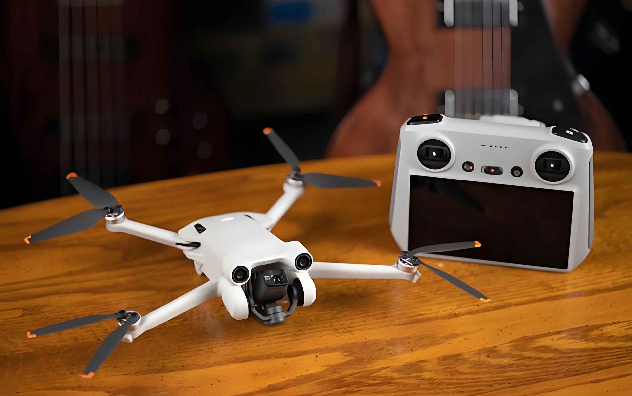
To validate the proposed tracking control method, we conducted simulation experiments in a laboratory environment that mimics real-world transmission line inspections. The experimental setup included a quadrotor drone, a remote controller, simulated transmission lines, and a PC for data processing. The drone was equipped with an image processing unit for real-time line detection, and the transmission lines were represented by 5 mm² single-strand copper wires installed between poles at a height of 200 cm. The PC ran simulations on a Windows 10 system with an Intel Xeon Silver 4114 CPU, NVIDIA GeForce GTX 1080Ti GPU, and 32 GB RAM, ensuring efficient computation for control algorithms and image analysis.
The drone was initialized at the starting point (120, 0, 30) in centimeters and commanded to take off vertically at a speed of 20 cm/s to reach the inspection start point (120, 0, 150). After stabilization, it began tracking the transmission line path. The desired trajectory was predefined, and the drone’s actual path was recorded for comparison. Image processing techniques, such as Hough transform, were applied to the captured images to extract line features and guide the tracking. Upon reaching the end point, the drone descended vertically to (120, 150, 0) at the same speed. The results showed that the actual trajectory closely matched the desired one across all axes, as illustrated in the position plots, confirming the effectiveness of the control method.
To test the robustness of the approach, we introduced scenarios with foreign objects interrupting the transmission lines. For example, an object was placed between y-axis coordinates 145–155 cm and z-axis coordinates 140–142 cm. The drone was programmed to detect such objects using image processing; if an object was on the line, it would hover and capture multiple angles before resuming inspection. In 10 repeated trials, the drone successfully detected and responded to objects in 9 cases, yielding an effectiveness rate of 90%. The hover data, including position deviations, are summarized in Table 3. The small variances in x, y, and z directions indicate precise hovering, though one trial failed due to poor image quality from lighting conditions, highlighting an area for improvement.
| Trial | X-axis Distance (cm) | Y-axis Distance (cm) | Z-axis Height (cm) |
|---|---|---|---|
| 1 | 77 | 146 | 138 |
| 2 | 80 | 143 | 136 |
| 3 | 75 | 140 | 139 |
| 4 | 75 | 152 | 131 |
| 5 | 76 | 155 | 140 |
| 6 | 90 | 148 | 141 |
| 7 | 85 | 143 | 137 |
| 8 | 81 | 140 | 141 |
| 9 | 83 | 152 | 139 |
| 10 | — | — | — |
| Average Variance | 4.9 | 3.3 | 1.4 |
The simulation results demonstrate that the drone technology-based control method enables accurate tracking of transmission lines, with the ability to handle interruptions and maintain stability. The finite-time controller ensured rapid convergence to the desired path, and the speed constraints were effectively enforced, preventing overshoot and ensuring safe operation. These findings underscore the potential of Unmanned Aerial Vehicles in automating power line inspections, reducing human effort, and increasing efficiency.
Conclusion
In conclusion, the proposed drone technology for transmission line inspection tracking control system has been validated through simulations, showing that the Unmanned Aerial Vehicle can accurately track desired trajectories under speed constraints. The finite-time position controller designed in this work facilitates efficient inspection of horizontal paths and handling of foreign object interruptions, with an overall effectiveness rate of 90%. This demonstrates the practicality of the method for real-world applications, offering improvements in inspection speed and reliability. However, the study has limitations, such as the laboratory-based simulation environment and limited sample size for foreign object scenarios, which may introduce biases. Future research should focus on testing the method in actual transmission line settings, incorporating more diverse environmental conditions, and expanding the dataset for object detection using neural networks. By addressing these aspects, the robustness and applicability of drone-based inspection systems can be further enhanced, paving the way for widespread adoption in power system maintenance.