
I developed a high-fidelity computational framework to study the aerodynamic noise and electric power behavior of UAV drone rotors. My motivation comes from the rapid growth of UAV drone applications in logistics, inspection, agriculture, surveillance, and urban air mobility. Although UAV drone platforms offer flexibility and efficiency, rotor noise remains a major barrier to public acceptance, regulatory approval, and sustainable operation in populated areas. The dominant source of UAV drone noise is the unsteady aerodynamic interaction between rotating blades and surrounding air. This interaction produces tonal noise at blade-passing frequencies and broadband noise from turbulence, wake shedding, blade-vortex interaction, and tip vortices. I therefore combined Detached Eddy Simulation (DES) with the Ffowcs Williams-Hawkings (FWH) acoustic analogy to resolve near-field turbulence and predict far-field sound. I applied this method to a single-rotor UAV drone, a quad-rotor UAV drone, and a quad-rotor UAV drone carrying a cargo box. I also calculated the electric power required by each configuration from torque and angular velocity.
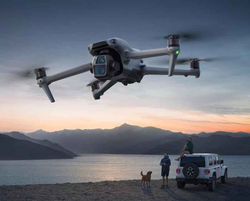
Research Motivation and Scope
I focused on three questions. First, how can I predict UAV drone rotor noise with greater physical fidelity than simplified empirical or steady RANS methods? Second, how does rotor count affect aerodynamic performance, noise radiation, and electric power consumption? Third, how does a delivery payload alter the aerodynamic and acoustic behavior of a UAV drone? To answer these questions, I used a hybrid numerical strategy. DES provides a balance between computational cost and turbulence resolution. FWH transforms near-field pressure and velocity information into far-field acoustic predictions. This combination allows me to identify tonal and broadband noise components and to relate them to flow structures around the rotor blades and wakes.
| Research Objective | Method Used | Key Output |
|---|---|---|
| Predict UAV drone rotor noise | DES for near-field turbulence and FWH for far-field acoustics | Sound pressure level, noise spectra, acoustic power distribution |
| Evaluate aerodynamic performance | Unsteady CFD with sliding mesh and refined blade grids | Lift, drag, torque, pressure, velocity, vorticity |
| Quantify electric power | Torque and angular velocity relationship | Power in watts for single, quad, and payload cases |
| Assess payload effects | Quad-rotor UAV drone with cargo box | Changes in lift, torque, noise, and power consumption |
Numerical Framework
I used the Navier-Stokes equations as the foundation of the flow solver. For incompressible and compressible regions, the continuity and momentum equations describe mass and momentum conservation. I then introduced DES as a hybrid turbulence model. In attached boundary-layer regions, DES behaves like a RANS model. In detached and wake regions, it behaves like a large eddy simulation. This is important for UAV drone rotors because the wake contains large unsteady structures that generate broadband noise, while the blade boundary layers contain small-scale turbulence that is expensive to resolve everywhere.
The continuity equation I used is:
$$ \frac{\partial \rho}{\partial t} + \nabla \cdot (\rho \mathbf{u}) = 0 $$
The momentum equation is:
$$ \frac{\partial (\rho \mathbf{u})}{\partial t} + \nabla \cdot (\rho \mathbf{u}\otimes\mathbf{u}) = -\nabla p + \nabla \cdot \boldsymbol{\tau} + \rho \mathbf{f} $$
For the RANS portion of DES, I used the time-averaged momentum equation:
$$ \frac{\partial (\rho \bar{\mathbf{u}})}{\partial t} + \nabla \cdot (\rho \bar{\mathbf{u}}\otimes\bar{\mathbf{u}}) = -\nabla \bar{p} + \nabla \cdot \boldsymbol{\tau}_{RANS} + \rho \mathbf{f} $$
For the LES portion, I applied a spatial filter to separate resolved and unresolved scales:
$$ \bar{f}(\mathbf{x},t) = \int_V f(\mathbf{x}’,t) W(\mathbf{x}-\mathbf{x}’) dV’ $$
The subgrid-scale stress in the LES region was modeled using the Smagorinsky approach:
$$ \tau_{ij}^{SGS} = -2\rho C_s^2 \Delta^2 \left(\bar{S}_{ij} – \frac{1}{3}\bar{S}_{kk}\delta_{ij}\right) $$
The DES momentum equation combines RANS and LES stresses:
$$ \frac{\partial (\rho \mathbf{u})}{\partial t} + \nabla \cdot (\rho \mathbf{u}\otimes\mathbf{u}) = -\nabla p + \nabla \cdot (\boldsymbol{\tau}_{RANS} + \boldsymbol{\tau}_{LES}) + \rho \mathbf{f} $$
The turbulent kinetic energy transport equation I used in the RANS region is:
$$ \frac{\partial(\rho k)}{\partial t} + \nabla \cdot (\rho \mathbf{u}k) = \nabla \cdot (\mu_T \nabla k) + P_k – \epsilon $$
The turbulent viscosity was obtained from:
$$ \nu_T = C_\mu \frac{k^2}{\epsilon} $$
I controlled the RANS-to-LES transition with a length-scale limiter:
$$ L_{DES} = \min(L_{RANS}, C_{DES}\Delta) $$
This limiter allows the model to resolve large turbulent eddies in the rotor wake while reducing computational expense near the blade surface. I also solved the energy equation for thermal transport, although heat transfer effects were not the main focus of my UAV drone noise analysis:
$$ \frac{\partial(\rho e)}{\partial t} + \nabla \cdot (\rho \mathbf{u}e) = \nabla \cdot (\kappa \nabla T) + \Phi + \rho \mathbf{f}\cdot\mathbf{u} $$
To enforce incompressibility in the pressure-velocity coupling, I used a pressure Poisson equation:
$$ \nabla^2 p = \frac{\nabla \cdot \rho \mathbf{u}}{\Delta t} $$
Ffowcs Williams-Hawkings Acoustic Analogy
After obtaining the near-field turbulent flow from DES, I used the FWH acoustic analogy to predict far-field noise. The FWH equation accounts for moving surfaces, which is essential for rotating UAV drone blades. I decomposed the acoustic sources into monopole, dipole, and quadrupole terms. For low-speed UAV drone rotors, dipole noise from unsteady blade pressure is usually dominant. Quadrupole noise from turbulence becomes more important at higher speeds or when wake interactions are strong.
The general FWH equation I used can be written as:
$$ \frac{\partial^2 p’}{\partial t^2} – c_0^2 \nabla^2 p’ = \frac{\partial}{\partial t}\left[\rho_0 v_n \delta(f)\right] – \frac{\partial}{\partial x_i}\left[l_i \delta(f)\right] + \frac{\partial^2}{\partial x_i \partial x_j}\left[T_{ij}H(f)\right] $$
The monopole contribution is:
$$ p_M(\mathbf{x},t) = \frac{1}{4\pi r}\dot{Q}\left(t-\frac{r}{c_0}\right) $$
The dipole contribution is:
$$ p_D(\mathbf{x},t) = \frac{1}{4\pi r}\frac{\partial}{\partial t}\left(\frac{\mathbf{F}\cdot\mathbf{r}}{r}\right) $$
The quadrupole contribution is:
$$ p_Q(\mathbf{x},t) = \frac{1}{4\pi r}\frac{\partial^2}{\partial x_i \partial x_j}\int_V \frac{T_{ij}}{r}dV $$
I computed the far-field pressure from surface integrals over the rotor blades:
$$ p_{far}(\mathbf{x},t) = \frac{1}{4\pi r}\int_S \left(\hat{\mathbf{n}}\cdot\frac{\partial \mathbf{u}}{\partial t}\right)dA $$
I converted pressure fluctuations into sound pressure level using:
$$ SPL = 20\log_{10}\left(\frac{p_{rms}}{p_{ref}}\right), \quad p_{ref}=20\,\mu Pa $$
I also examined blade-passing frequency noise, which appears at harmonics of the rotor rotation rate:
$$ f_{BPF} = \frac{N_b \Omega}{2\pi} $$
where \(N_b\) is the number of blades and \(\Omega\) is angular velocity. This tonal component is one of the most recognizable features of UAV drone noise.
| Acoustic Source | Physical Origin | Relevance to UAV Drone Noise |
|---|---|---|
| Monopole | Volume displacement and compressibility | Low-frequency noise, especially from blade thickness and displacement |
| Dipole | Unsteady pressure on solid surfaces | Dominant tonal and loading noise from rotor blades |
| Quadrupole | Turbulent fluctuations in the flow | Broadband noise from wakes, tip vortices, and turbulence |
Single Rotor UAV Drone Simulation
I first simulated an isolated single-rotor UAV drone at 8500 RPM. I selected this rotational speed because it represents a demanding operating condition and provides a baseline for later multi-rotor and payload studies. I divided the computational domain into a rotating region around the rotor and a static far-field region. I used a sliding mesh interface to represent rotor motion. I refined the mesh near the blade surfaces to capture boundary-layer effects and pressure gradients. I set a velocity inlet, a pressure outlet, no-slip rotor walls, and far-field boundaries that minimized acoustic reflections.
| Parameter | Value or Setting |
|---|---|
| Rotational speed | 8500 RPM |
| Angular velocity | 890.12 rad/s |
| Turbulence model | DES with RANS near walls and LES in detached regions |
| Acoustic model | Ffowcs Williams-Hawkings analogy |
| Mesh motion | Sliding mesh |
| Boundary conditions | Velocity inlet, pressure outlet, no-slip rotor wall, far-field symmetry |
| Initialization | Hybrid initialization with residual and force monitoring |
From the aerodynamic solution, I observed that lift and torque increase strongly with rotational speed. The pressure distribution showed high positive pressure on the pressure side and high negative pressure on the suction side, with the strongest gradients near the blade tip. The velocity field showed a clear wake downstream of the rotor, and the axial velocity magnitude decreased with distance as kinetic energy dissipated. The vorticity field revealed coherent tip vortices and wake structures that are important for broadband noise generation.
I calculated the electric power of the single rotor using:
$$ P = T\omega $$
where \(T\) is torque and \(\omega\) is angular velocity. For 8500 RPM:
$$ \omega = \frac{2\pi \times 8500}{60} = 890.12\,\text{rad/s} $$
Using the simulated torque of \(0.099\,\text{N}\cdot\text{m}\), I obtained:
$$ P_{single} = 0.099 \times 890.12 = 88.11\,\text{W} $$
| Single-Rotor UAV Drone Quantity | Value |
|---|---|
| Lift | 6.362 N |
| Torque | 0.099 N·m |
| Electric power | 88.11 W |
| Dominant noise type at low frequency | Tonal blade-passing noise |
| Dominant noise type at high frequency | Broadband turbulence noise |
| Maximum acoustic activity region | Rotor tip and wake |
The acoustic results showed that the sound pressure level peaked near the rotor tip and wake region. The noise spectrum contained strong tonal peaks at blade-passing frequencies and a broadband floor at higher frequencies. The one-third octave analysis showed a maximum near the mid-frequency range and a gradual decay at higher frequencies. I also used the Q-criterion to visualize vortex structures. The results showed that tip vortex shedding is a major contributor to UAV drone noise, which suggests that blade tip geometry, trailing-edge serrations, and wake control could reduce noise.
Quad-Rotor UAV Drone Analysis
I then extended the simulation to a quad-rotor UAV drone. In this configuration, two rotors rotate clockwise and two rotate counterclockwise. The adjacent rotors rotate in opposite directions to balance torque and reduce unwanted yaw. The wake from each rotor interacts with the wakes of neighboring rotors. These interactions change the pressure field, alter the aerodynamic loading, and modify the acoustic radiation. I kept the rotational speed at 8500 RPM so that I could compare the quad-rotor results directly with the single-rotor baseline.
The quad-rotor domain contained four rotating zones and one stationary far-field zone. I refined the mesh near each rotor and in the shared wake region between rotors. The rotating zones were connected to the stationary zone through sliding mesh interfaces. I used the same DES-FWH workflow as in the single-rotor case. The main difference was the inclusion of rotor-to-rotor interference and wake merging.
| Quad-Rotor Setup Feature | Description |
|---|---|
| Number of rotors | 4 |
| Rotation directions | 2 clockwise and 2 counterclockwise |
| Rotational speed | 8500 RPM |
| Rotating domains | One per rotor |
| Stationary domain | Far-field region surrounding all rotors |
| Dominant flow feature | Wake interaction and pressure interference |
| Acoustic method | FWH with near-field data from DES |
The lift curves for the four rotors showed similar trends. Lift increased with rotational speed, and the maximum values appeared near the blade tips where pressure differences were largest. The drag curves increased approximately linearly with rotational speed, which indicates a trade-off between aerodynamic force generation and energy consumption. The pressure distribution in the rotating domain showed unsteady fluctuations downstream of each rotor. I observed that the wake region between rotors contained complex pressure patterns caused by adjacent rotor interference.
The velocity contours showed that the wake from each rotor merged with the surrounding flow and with neighboring wakes. The axial velocity was highest near the rotor tips and decreased downstream. The Q-criterion visualization showed multiple vortex structures, including tip vortices from each rotor and interacting wake vortices. These structures are important because they generate broadband noise and can amplify tonal noise through unsteady blade loading.
For the quad-rotor UAV drone, I calculated the total electric power from the torque per rotor:
$$ P_{quad} = N_{rotor} T_{rotor}\omega $$
With four rotors, each producing \(0.409\,\text{N}\cdot\text{m}\) at 8500 RPM, I obtained:
$$ P_{quad} = 4 \times 0.409 \times 890.12 = 364.01\,\text{W} $$
| Quad-Rotor UAV Drone Quantity | Value |
|---|---|
| Total lift | 24.547 N |
| Torque per rotor | 0.409 N·m |
| Total electric power | 364.01 W |
| Noise behavior | Higher than single rotor, but not a simple fourfold increase |
| Main acoustic hotspots | Rotor tips and merged wake regions |
| Main aerodynamic challenge | Wake interference and pressure unsteadiness |
The quad-rotor noise was more intense than the single-rotor noise, especially near the rotors. However, the increase was not proportional to the number of rotors. This happens because acoustic sources partially overlap, interfere, and distribute across different directions. Some wake interactions increase local turbulence, while others may cause phase differences that reduce far-field sound at certain observer positions. I found that rotor spacing, rotational direction, and wake merging are therefore important design variables for UAV drone noise control.
Case Study: Effects of Goods Delivery on UAV Drone Aerodynamics and Acoustics
I next studied a quad-rotor UAV drone carrying a cargo box. Delivery UAV drones must operate with payloads that change mass, center of gravity, drag, and wake structure. I modeled a cargo box attached below the quad-rotor platform and kept the rotors at 8500 RPM. I used the same DES-FWH framework so that the results could be compared with the unloaded quad-rotor case. The computational domain included four rotating zones and one stationary zone. The total mesh size for the payload case was approximately 10.61 million cells, with refined regions around the rotors, the cargo box, and the shared wake.
| Payload Case Setup | Value or Description |
|---|---|
| UAV drone configuration | Quad-rotor with cargo box |
| Cargo box dimensions | 506 mm length × 506 mm width × 480 mm height |
| Rotational speed | 8500 RPM |
| Total mesh size | Approximately 10.61 million cells |
| Rotating zones | 4 |
| Stationary zone | 1 far-field region |
| Acoustic prediction | FWH acoustic analogy |
The aerodynamic results showed that the cargo box changes the flow around the UAV drone significantly. The box introduces an additional bluff body into the flow, which increases drag and alters the wake structure. The lift distribution becomes less symmetric because the payload affects the local pressure field and the interaction between the rotor wakes and the cargo box. The velocity field showed higher turbulence intensity in the wake region downstream of the payload. The pressure contours showed stronger local gradients near the box and near the rotor tips. These changes increase the unsteady loading on the rotors and can reduce aerodynamic efficiency.
The acoustic analysis showed that the payload increases low-frequency noise. The cargo box produces additional wake turbulence, and this turbulence interacts with the rotor wakes. The one-third octave band analysis showed that the noise levels remain concentrated at low frequencies, with peaks associated with rotor tip vortices and wake turbulence. Compared with the unloaded quad-rotor UAV drone, the loaded configuration emitted higher noise in the near field. However, in the far field, some monitoring points showed slightly lower values because of acoustic interference and directivity changes. This means that payload effects on UAV drone noise are not uniform in all directions.
| Monitoring Point | Single Rotor SPL (dB) | Quad Rotor SPL (dB) | Quad Rotor with Cargo SPL (dB) |
|---|---|---|---|
| 1 | 77.8684 | 102.1790 | 103.8080 |
| 2 | 75.0846 | 100.3270 | 100.2310 |
| 3 | 72.8449 | 98.9389 | 98.0788 |
| 4 | 70.9673 | 97.5866 | 96.3697 |
| 5 | 69.5030 | 96.3568 | 94.9115 |
| 6 | 46.7105 | 74.7176 | 72.4137 |
I calculated the electric power for the loaded quad-rotor UAV drone using the same torque-angular velocity relation. The cargo box increased the torque required per rotor to approximately \(0.422\,\text{N}\cdot\text{m}\). The total power became:
$$ P_{payload} = 4 \times 0.422 \times 890.12 = 375.58\,\text{W} $$
The percentage increase relative to the unloaded quad-rotor case was:
$$ \Delta P\% = \frac{375.58 – 364.01}{364.01} \times 100\% \approx 3.17\% $$
| Configuration | Lift (N) | Torque (N·m) | Electric Power (W) |
|---|---|---|---|
| Single rotor | 6.362 | 0.099 | 88.11 |
| Quad rotor | 24.547 | 0.409 | 364.01 |
| Quad rotor with goods effect | 25.835 | 0.422 | 375.58 |
The payload case therefore showed a 3.17% increase in electric power consumption. This value is small but important for delivery UAV drones because flight time, battery size, and thermal management are all sensitive to power demand. The cargo box also increased lift because the rotors had to generate additional thrust to support the payload and maintain stability. The combined aerodynamic and acoustic effects show that payload integration is not only a structural or mass problem. It is also a flow-control and noise-control problem.
Discussion
My results show several consistent trends. First, rotor speed is a primary factor in both aerodynamic force and noise. Lift and torque increase with rotational speed, and noise increases because blade-passing tones and turbulence-induced broadband noise become stronger. Second, multi-rotor configurations produce more noise than a single rotor, but the increase is not simply proportional to rotor count. Acoustic interference, directivity, and wake interaction all affect the total radiated sound. Third, a payload changes the wake structure and increases low-frequency noise, especially in the near field. Fourth, electric power consumption rises with payload because the rotors must produce more torque to maintain the same rotational speed and flight condition.
I can summarize the acoustic scaling behavior using a simplified relation. If multiple rotors behaved as independent and perfectly coherent sources, the sound pressure level would increase by:
$$ \Delta SPL = 10\log_{10}(N) $$
For four rotors, this would be about \(6\,\text{dB}\). In my simulations, the increase from single rotor to quad rotor was larger in the near field because of closeness to sources and wake interaction, but it was still not a simple multiplication of acoustic power by four. This confirms that interference and directivity are essential for UAV drone noise prediction.
| Observation | Single Rotor | Quad Rotor | Quad Rotor with Payload |
|---|---|---|---|
| Aerodynamic complexity | Isolated blade and wake | Multiple interacting wakes | Multiple wakes plus bluff-body cargo wake |
| Noise sources | Blade tones and tip vortices | Blade tones, tip vortices, wake interaction | Blade tones, wake interaction, cargo-induced turbulence |
| Near-field noise | Lowest | Higher | Highest in most near-field points |
| Far-field noise trend | Decreases with distance | Decreases with distance but remains high | Can decrease or shift due to interference |
| Electric power | 88.11 W | 364.01 W | 375.58 W |
The distance effect was also clear. As the receiver moved farther from the UAV drone, the sound pressure level decreased. This is expected because acoustic intensity decays with distance, and the radiated field becomes more diffuse. However, the decrease was not identical for all configurations. The payload case showed stronger near-field noise but weaker far-field noise at some points, which indicates that the cargo box redirected acoustic energy and changed the directivity pattern.
For UAV drone design, my findings suggest several practical implications. Rotor blade tips should be designed to reduce coherent tip vortex shedding. Trailing-edge treatments, blade sweep, and optimized blade planforms may reduce broadband noise. Multi-rotor spacing should be selected to avoid strong wake merging and constructive acoustic interference. Payload placement should be studied carefully because a cargo box can increase drag, disturb rotor inflow, and modify noise radiation. Finally, power budgets for delivery UAV drones should include not only payload mass but also the aerodynamic penalty caused by the payload shape and wake interaction.
Conclusion and Future Work
I established a DES-FWH framework for UAV drone rotor noise and electric power simulation. I applied it to a single rotor, a quad rotor, and a quad rotor with a cargo box. The single-rotor UAV drone produced 88.11 W at 8500 RPM. The quad-rotor UAV drone produced 364.01 W. The quad-rotor UAV drone with a cargo box produced 375.58 W, which is a 3.17% increase over the unloaded quad-rotor case. The acoustic results showed that tonal noise dominates at low frequencies, broadband noise dominates at higher frequencies, and the strongest acoustic activity occurs near rotor tips and wakes. The quad-rotor configuration generated higher noise than the single rotor, but the increase was not fourfold because of interference and directivity. The payload increased near-field noise and altered far-field noise distribution.
My work provides a foundation for quieter and more efficient UAV drone design. In future work, I plan to extend the framework to transient maneuvers, variable rotational speeds, crosswinds, atmospheric turbulence, and urban environments with buildings and ground reflections. I also intend to validate the simulations with wind-tunnel and flight-test measurements. Additional work should explore machine learning surrogate models and multi-objective optimization to balance aerodynamic efficiency, acoustic comfort, and electric power consumption. These steps will help UAV drones become more acceptable for urban delivery, inspection, and low-altitude mobility.
| Final Summary | Key Finding |
|---|---|
| Noise mechanism | Tonal blade-passing noise and broadband wake turbulence noise dominate UAV drone rotors |
| Single-rotor power | 88.11 W at 8500 RPM |
| Quad-rotor power | 364.01 W at 8500 RPM |
| Payload power | 375.58 W, a 3.17% increase |
| Multi-rotor effect | Higher noise than single rotor, but not simply four times higher |
| Payload effect | Increases near-field noise, alters far-field directivity, and increases power demand |
| Best design direction | Optimize blade tips, rotor spacing, payload placement, and wake control for quieter UAV drone operation |