
Unmanned aerial vehicles (UAVs), particularly multirotor platforms, have demonstrated significant potential in last-mile logistics and express delivery services. The rapid growth of e-commerce and the increasing demand for instant delivery have placed tremendous pressure on traditional ground transportation systems. Small quadrotor cargo UAVs offer a flexible and efficient solution for urban and rural logistics, enabling rapid transport of packages while bypassing traffic congestion. However, the limited endurance and relatively high energy consumption of electric quadrotor UAVs remain critical barriers to their widespread commercial deployment. Reducing flight energy consumption is not only a technical challenge but also an economic and environmental necessity. In my research, I focus on developing an energy optimization control strategy for a small quadrotor cargo UAV named X760. The core idea is to exploit the fact that the power system of a multirotor UAV has different efficiency characteristics under different load conditions. By dynamically switching between different rotor configurations and optimizing the motor speed for each flight phase, the UAV can operate closer to its optimal energy efficiency boundary, resulting in substantial energy savings.
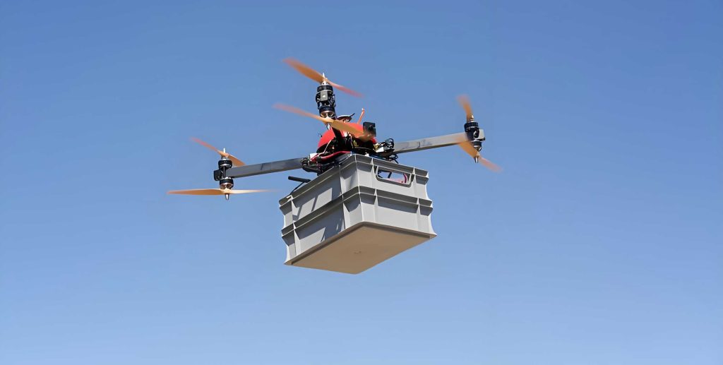
The work presented in this paper covers the complete cycle of analysis, design, implementation, and experimental validation. Starting with an in-depth study of the energy consumption characteristics of quadrotor cargo UAVs, I establish mathematical models for the power required during takeoff, climb, level flight, hover, descent, and return phases. Based on these models, I propose a configuration-scheduling strategy that selects among three distinct flight configurations: single-upper-propeller mode for light loads, dual-coaxial-propeller mode for medium and heavy loads, and single-lower-propeller mode for empty return flights. The X760 prototype was designed using CATIA software and built with a Pixhawk flight controller. Extensive flight tests were carried out under no-load, 1500 g load, and 4000 g load conditions. The experimental results demonstrate that the proposed energy optimization control strategy reduces energy consumption by approximately 7.5%, 16%, and 23% respectively compared with the baseline fixed-configuration strategy. These findings indicate that the proposed control approach is both safe and highly effective for improving the energy efficiency of small cargo UAVs.
1. Introduction
In the past two decades, unmanned aerial vehicles (UAVs) have evolved from niche military tools to indispensable assets in civilian applications. Among the various types of UAVs, multirotor platforms have gained exceptional popularity due to their vertical takeoff and landing capabilities, mechanical simplicity, and high maneuverability. In particular, quadrotor cargo UAVs are considered a promising solution for the “last kilometer” delivery problem in logistics. Companies such as JD.com, SF Express, and Amazon have already experimented with UAV delivery systems, while numerous startups are developing dedicated cargo UAV platforms. The market demands for small quadrotor cargo UAVs are increasing, yet their operational viability is hindered by limited battery life and high energy costs.
The energy consumption of an electric quadrotor UAV is a central issue that affects endurance, payload capacity, operating cost, and environmental footprint. Unlike fixed-wing aircraft that benefit from efficient lift generation during cruise, multirotor UAVs must continuously consume power to hover and maneuver. For cargo missions, the additional weight of the payload significantly increases the power required to maintain flight, which accelerates battery depletion. Therefore, optimizing the flight energy consumption of cargo UAVs is of paramount importance. Many researchers have explored aerodynamic optimization, lightweight materials, advanced control algorithms, and task planning methods to reduce energy consumption. However, most existing studies focus on a fixed propulsion architecture and control algorithm improvements without considering the possibility of adapting the propulsion system configuration to the instantaneous load condition during a mission.
In this research, I propose a novel energy optimization control strategy for a small quadrotor cargo UAV based on dynamic configuration switching and load-aware motor speed scheduling. The key observation is that the energy efficiency of a brushless motor and propeller system is highly dependent on the operating point, which is determined by the required thrust and the number of active rotors. For a given total takeoff weight, there exists an optimal configuration that places the motors in their most efficient operating region. By intelligently selecting the appropriate configuration and adjusting motor speeds, the UAV can significantly reduce the energy consumption during each segment of a delivery mission. This strategy not only improves endurance but also reduces operating costs and contributes to green logistics.
2. Energy Consumption Analysis of Small Quadrotor Cargo UAVs
2.1 Coaxial Double-Ducted Power System Structure
The X760 cargo UAV adopts a four-axis eight-rotor structure, where each arm contains two rotors arranged coaxially with opposite rotation directions. This configuration, known as a coaxial double-rotor or coaxial twin-rotor setup, provides inherent redundancy: if one rotor fails, the other on the same shaft can still produce thrust to maintain safe flight. Compared with a conventional quadrotor, the coaxial structure offers higher lifting capacity and better safety margins. Compared with a traditional eight-rotor layout with eight separate arms, the coaxial arrangement reduces the overall footprint and structural weight, which is beneficial for energy efficiency. However, the coaxial rotor design also introduces aerodynamic interference between the upper and lower propellers, which can degrade the overall efficiency. To mitigate this, careful attention must be paid to the propeller spacing and the optimization of relative rotation directions.
2.2 Definition and Characterization of Flight Energy Consumption
The total flight energy consumption of an electric quadrotor UAV is defined as the electrical energy consumed during a complete flight mission, typically measured in watt-hours (Wh). The flight mission consists of multiple phases: takeoff, climbing, level flight, hovering, descending, and landing. The rate of energy consumption is the instantaneous power, which can be decomposed into dynamic power consumed by the propulsion system and static power consumed by the onboard electronics (flight controller, sensors, and communication equipment). In my analysis, the static power is considered a constant term, while the dynamic power varies according to flight conditions and load.
The total energy consumption \(E_{\text{flight}}\) for a mission spanning from time \(t_1\) to \(t_2\) is given by:
$$E_{\text{flight}} = \int_{t_1}^{t_2} \left( P_{\text{total}}(t) + P_{\text{electronics}} \right) \, dt$$
where \(P_{\text{total}}(t)\) is the instantaneous dynamic power consumed by the propulsion system, and \(P_{\text{electronics}}\) is the constant power used by avionics and ancillary equipment. In industrial practice, the specific energy consumption, i.e., energy per unit time, is often used as the evaluation index. It can be expressed as:
$$\bar{P} = \frac{E_{\text{flight}}}{T_{\text{flight}}}$$
In this research, the flight energy consumption is measured experimentally by recording the total flight time with a timer and using a battery charger to determine the amount of charge drawn from the battery during each flight. Multiplying the consumed ampere-hours by the nominal battery voltage (22.2 V) yields the energy consumption in watt-hours.
2.3 Main Factors Influencing Energy Consumption
The energy consumption of a small cargo UAV is affected by multiple factors. Through a comprehensive review of the technical literature and my experimental observations, the most prominent factors are:
| Factor | Description | Impact on Energy |
|---|---|---|
| Flight state | Different phases such as hovering, climbing, descending, and level flight | Climbing and hovering require high thrust; descending consumes significantly less energy |
| Payload weight | The total mass that the UAV must lift, including cargo and battery | Higher payload increases required thrust, raises motor speed, and shifts operating points away from peak efficiency |
| Battery system | Energy density, discharge efficiency, and thermal behavior | A heavier battery reduces payload capacity but a battery with higher energy density increases range and reduces energy loss |
| Propulsion system | Motor efficiency, propeller aerodynamic performance, and electronic speed controller characteristics | Operating motors near their peak efficiency region minimizes losses from heat and other inefficiencies |
| Flight speed and trajectory | Velocity and path planning directly influence aerodynamic drag and power requirements | Excessively high speeds increase drag and power; very low speeds extend flight time and increase energy consumption |
2.4 Relationship Between Payload and Energy Consumption
The load weight is one of the most critical parameters affecting the energy consumption of a quadrotor UAV. The total takeoff weight is the sum of the empty weight, battery weight, and payload weight. To maintain level flight, the lifting force produced by the propellers must equal the total weight. According to momentum theory and blade element analysis, the thrust \(L\) produced by a propeller can be expressed as:
$$L = \frac{1}{2} \rho v^2 C_L A$$
where \(\rho\) is the air density, \(v\) is the induced velocity at the propeller disc, \(C_L\) is the lift coefficient, and \(A\) is the propeller disc area. In a fixed-pitch propeller system, \(C_L\) and \(A\) are constant. To increase the lift, the motor must increase the rotational speed, which raises the induced velocity and, consequently, the power consumption. When the load is light, running all eight rotors may place each motor at a very low throttle level, which is inefficient because the motor’s electronic controller incurs fixed losses and the propeller operates at a low efficiency region. Conversely, when the load is heavy, a four-rotor configuration may force the motors to operate at near maximum throttle, where efficiency also degrades and current rises rapidly, leading to additional \(I^2R\) losses. Therefore, the key to optimization is to match the number of active rotors and their operating speeds to the actual load.
2.5 Relationship Between Flight Time and Energy Consumption
For a delivery mission with a fixed distance, the flight time is inversely proportional to the ground speed. Increasing the speed generally reduces flight time but increases the power consumption due to higher induced drag and parasitic drag. The total energy is the integral of power over time; thus, there exists an optimal speed that minimizes the energy consumption for a given route. This optimization is particularly relevant in the level-flight phase. In my analysis, I account for both the flight speed and the duration to determine the energy-optimal motor speed for each phase. Additionally, the battery selection influences the total energy available, and an improper battery weight may either limit payload or cause excessive structural weight, both of which lead to higher energy consumption.
3. Structural and Configuration Optimization of the X760 Cargo UAV
3.1 Design Objectives and Specifications
The X760 cargo UAV is designed to operate in typical urban and rural delivery scenarios. Its mission profile consists of vertical takeoff from a loading station, climbing to a cruise altitude of approximately 200 meters, level flight to the destination waypoint, a short hover for package release, and vertical descent for landing. After unloading, the UAV returns to the origin using the same procedure. The design target is to carry payloads ranging from 0 to 8 kg, with an optimal load of 4 kg. A market survey indicates that the most common payload range for small cargo UAVs is between 1 and 4 kg, comprising 55% of tasks, while 4–8 kg accounts for 35%. The X760 is therefore optimized for these two segments. The main technical specifications are summarized in Table 1.
| Parameter | Unit | Design Requirement |
|---|---|---|
| Overall dimensions | cm | ≤ 90 × 60 × 40 |
| Empty weight (without battery) | kg | 3.5 |
| Standard payload | kg | ≤ 8 |
| Flight endurance | min | ≥ 20 |
| Maximum flight altitude | m | ≤ 300 |
| Maximum level flight speed | m/s | ≤ 10 |
| Maximum climb speed | m/s | ≤ 5 |
| Maximum range | km | ≤ 12 |
| Maximum descent speed | m/s | ≤ 3 |
3.2 Flight Configuration Design
The X760 uses a four-axis eight-rotor coaxial layout. The two rotors on each axis share the same centerline and rotate in opposite directions. The upper arm houses a 17-inch propeller, while the lower arm carries a 17-inch or 18-inch propeller depending on the expected load. The overall structure is designed to allow the flight controller to selectively enable or disable the upper and lower rotors independently. Based on the load mass, the X760 can switch between three flight configurations:
| Configuration | Active rotors | Typical load range | Advantages |
|---|---|---|---|
| Configuration 1 | Upper four rotors | 1–2 kg | Light weight, high efficiency at low loads |
| Configuration 2 | All eight rotors (upper and lower) | 3–8 kg | High lifting capacity, redundancy, balanced efficiency |
| Configuration 3 | Lower four rotors | 0 kg (empty return) | Minimum number of active rotors, very low energy consumption |
Configuration 1 is most effective when the UAV is carrying a light load. In this mode, only the upper propellers are active. Because the total weight is modest, the upper motors operate at a throttle level that corresponds to their maximum efficiency. Configuration 2 is used for medium and heavy loads. Both upper and lower rotors work together, distributing the total thrust among eight motors, each of which remains within its optimal or near-optimal efficiency band. Configuration 3 is reserved for empty return flights. Only the lower propellers are used, which further reduces the number of active motors and therefore the static energy losses. It is worth noting that during configuration switching, the inactive rotors are allowed to freewheel, thus they do not contribute to thrust but also do not generate excessive drag because of their low profile. This clever design mitigates the “dead weight” problem that would otherwise arise when a set of motors is not used.
3.3 Motor and Propeller Selection Optimization
The selection of motors and propellers is critical in determining the energy efficiency of the propulsion system. The X760 uses a brushless DC motor with a nominal voltage of 22.2 V (6S battery). After comparing several candidate motors, the 5010 KV340 motor was selected. This motor has a maximum continuous power of 730 W and a recommended thrust range of 2000–3000 g per propeller. The motor is among the lightest in its class, weighing only 182 g, which helps to minimize structural weight. The motor’s efficiency characteristics are shown in Table 3, which lists the thrust and efficiency at different throttle levels for two propeller sizes (17.5-inch and 18.5-inch).
| Propeller | Throttle (%) | Current (A) | Power (W) | Thrust (g) | Efficiency (g/W) |
|---|---|---|---|---|---|
| 1755 | 50 | 4.4 | 97.68 | 1269 | 12.99 |
| 1755 | 60 | 6.6 | 146.52 | 1723 | 11.76 |
| 1755 | 70 | 10.6 | 235.32 | 2316 | 9.84 |
| 1755 | 80 | 15.4 | 341.88 | 2650 | 7.75 |
| 1755 | 90 | 22.0 | 488.40 | 3215 | 6.58 |
| 1755 | 100 | 26.5 | 588.30 | 3600 | 6.12 |
| 1855 | 50 | 6.5 | 144.30 | 1728 | 11.98 |
| 1855 | 60 | 10.0 | 222.00 | 2340 | 10.54 |
| 1855 | 70 | 15.9 | 352.98 | 2675 | 7.58 |
| 1855 | 80 | 20.6 | 457.32 | 3240 | 6.27 |
| 1855 | 90 | 27.7 | 614.94 | 3855 | 6.27 |
| 1855 | 100 | 33.0 | 732.60 | 4300 | 5.87 |
From Table 3, the highest efficiency (12.99 g/W) occurs at 50% throttle with the 17.5-inch propeller. This operating point corresponds to a thrust of about 1269 g per motor. During light-load flight, the X760 with a total takeoff weight of 5.5–7 kg requires roughly 1.4–1.75 kg of thrust per motor when only four motors are active. This falls near the 60% throttle region, where efficiency is still high (about 11.76 g/W). For heavier loads, activating all eight motors reduces the required thrust per motor to about 1.2–1.5 kg, again placing operation near the 50% throttle point. Thus, the propulsion system is well-matched to the intended operating regions.
3.4 Battery Configuration Optimization
The battery is another critical component that balances weight and energy capacity. Using the design payload and structural data, the X760 empty weight (without battery) is determined to be 3.5 kg. For a maximum takeoff weight of 11.5 kg (empty weight plus battery plus 8 kg payload), the total thrust requirement is distributed among eight motors in configuration 2, giving a per-motor thrust of about 1.4 kg. Considering a factor of safety and the desire to keep motors in their high-efficiency region, a battery weight of 2.0–2.5 kg is appropriate. After surveying available lithium polymer batteries, the 6S 22,000 mAh 15C solid-state lithium battery was chosen. The key parameters are listed in Table 4.
| Nominal voltage (V) | Full charge voltage (V) | Cut-off voltage (V) | Discharge rate (C) | Weight (g) | Dimensions (mm) |
|---|---|---|---|---|---|
| 22.2 | 25.2 | 16.8 | 15 | 1930 | 65 × 75 × 200 |
The selected battery provides sufficient capacity for a 20-minute flight with a 4 kg payload. The battery weight of 1.93 kg fits within the target range. During the test flights, the battery voltage was monitored, and the flight was terminated when the voltage dropped to 21.6 V to protect the battery from deep discharge and ensure safety.
3.5 Coaxial Rotor Spacing Optimization
For coaxial rotors, the vertical separation between the upper and lower propellers significantly affects aerodynamic efficiency. If the spacing is too small, the downwash of the upper rotor interferes with the lower rotor, reducing thrust and increasing induced drag. If the spacing is too large, the structural weight and inertia increase. Based on blade element momentum theory and empirical data, the optimal dimensionless spacing \(H/D\) (spacing divided by propeller diameter) is typically in the range of 0.1 to 0.2. For the X760, which uses propellers with diameters of 17 and 18 inches (432–457 mm), the optimal spacing is approximately 86–91 mm. The design uses a spacing of 88.6 mm, achieved by setting the height of the motor and mounting plates. This choice ensures that the coaxial interference remains within acceptable limits while maintaining a compact and rigid structure.
4. Energy Optimization Flight Scheduling Strategy
4.1 Mission Profile and Power Decomposition
For the X760 cargo UAV, a typical delivery mission comprises five phases: takeoff/climb, level flight, hover, descent, and return. During each phase, the power consumption is composed of different physical components. In my framework, the total instantaneous power during climb, forward flight, and hover can be expressed as:
$$P_{\text{climb}} = P_{\text{lift}} + P_{\text{profile}} + P_{\text{parasite}}$$
$$P_{\text{forward}} = P_{\text{induced}} + P_{\text{profile}} + P_{\text{parasite}}$$
$$P_{\text{hover}} = P_{\text{lift}} + P_{\text{profile}}$$
where:
- \(P_{\text{lift}}\) is the power needed to generate thrust and support the weight,
- \(P_{\text{profile}}\) is the power required to overcome the drag of the rotating propeller blades,
- \(P_{\text{induced}}\) is the induced power due to the acceleration of air through the rotor disc,
- \(P_{\text{parasite}}\) is the power needed to overcome drag on the fuselage and other non-lifting components.
4.2 Climb Phase Energy Model
For a steady climb with constant vertical speed \(v_{\text{climb}}\), the lift power is given by:
$$P_{\text{lift}} = \frac{(m g + m a) \, v_{\text{climb}}}{\eta}$$
where \(m\) is the total mass, \(g\) is the gravitational acceleration, \(a\) is the vertical acceleration (assumed zero in steady climb), and \(\eta\) is the rotor efficiency. The profile power is:
$$P_{\text{profile}} = \frac{1}{2} \rho C_D A (\Omega R)^3$$
where \(\rho\) is air density, \(C_D\) is the drag coefficient of the blades, \(A\) is the total rotor disc area, \(\Omega\) is the angular velocity of the motor, and \(R\) is the rotor radius. The parasite power is:
$$P_{\text{parasite}} = \frac{1}{2} \rho C_{D,\text{body}} A_{\text{body}} v_{\text{climb}}^3$$
The total energy consumed during climb can be integrated over the climbing duration. Since the climb height is fixed (200 m), the climb time is inversely proportional to the climb speed. Therefore, the climb energy has a minimum with respect to motor speed, as will be derived later.
4.3 Level Flight Energy Model
During level flight, the UAV flies at a constant speed \(v_{\text{forward}}\) and a pitch angle \(\theta\) with respect to the horizon. The thrust vector has a vertical component balancing the weight and a horizontal component overcoming the drag. The induced power is:
$$P_{\text{induced}} = \frac{(m g)^2}{\sqrt{2 \rho A} \, v_{\text{ind}}}$$
where \(v_{\text{ind}}\) is the induced velocity, which itself depends on thrust. The parasite power for level flight is:
$$P_{\text{parasite}} = \frac{1}{2} \rho C_{D,\text{body}} A_{\text{body}} v_{\text{forward}}^3$$
The power consumption during level flight is a function of the motor speed and the pitch angle. For a given distance and altitude, the flight time is inversely proportional to the forward speed. Thus, the total energy can be minimized by selecting the optimal speed and configuration.
4.4 Hover Phase Energy Model
In hover, the UAV remains motionless. The required thrust equals the total weight, and the induced power is simply:
$$P_{\text{hover}} = \frac{m g \, v_{\text{ind}}}{\eta} + \frac{1}{2} \rho C_D A (\Omega R)^3$$
The hover energy is proportional to the hover time. For mission optimization, reducing the hover time is the most effective way to minimize hover energy, but for a fixed hover duration, selecting the right configuration ensures that the motors operate at their most efficient speed.
4.5 Descent Phase Energy Model
During descent, the potential energy of the UAV is converted into kinetic energy, which reduces the required power. The descent power can be written as:
$$P_{\text{descent}} = P_{\text{lift}} + P_{\text{profile}} – P_{\text{gravity}}$$
where \(P_{\text{gravity}} = m g v_{\text{descent}}\) is the power contribution from gravity. Since the descent speed is limited to 3 m/s for safety, the energy consumption in this phase is significantly lower than in the climb or hover phases. In my optimization, the descent phase is not subject to aggressive energy minimization; instead, the focus is on safe and controlled landing.
4.6 Optimal Speed and Configuration Scheduling
To find the optimal motor speed, I set up the total energy for each phase as a function of the motor angular velocity \(\Omega\). For example, during climb, combining the lift, profile, and parasite power expressions, the total climb energy can be written as:
$$E_{\text{climb}}(\Omega) = \left[ \frac{m g \sqrt{\frac{2 m g}{\rho A}}}{\eta \sqrt{\Omega}} + \frac{1}{2} \rho C_D A R^3 \Omega^3 + \frac{1}{2} \rho C_{D,\text{body}} A_{\text{body}} \left( \frac{2 m g}{\rho A \Omega} \right)^{3/2} \right] \cdot \frac{200}{v_{\text{climb}}(\Omega)}$$
To minimize \(E_{\text{climb}}\), I take the derivative with respect to \(\Omega\) and set it to zero. The solution yields the optimal motor speed \(\Omega_{\text{opt}}\). A similar approach is used for level flight and hover. For each load condition, the optimal configuration is the one that results in the lowest total energy consumption across all mission phases. This decision is implemented in the firmware of the flight controller, which reads the payload weight from a load cell sensor and selects the precomputed configuration and motor speed setpoints.
Table 5 summarizes the calculated optimal motor speeds and selected configurations for three representative load conditions.
| Load condition | Total takeoff weight (kg) | Configuration | Climb speed (m/s) | Level flight speed (m/s) | Hover motor speed (rad/s) |
|---|---|---|---|---|---|
| Empty (0 kg) | 5.5 | 3 | 4.2 | 8.5 | 67.3 |
| Light (1.5 kg) | 7.0 | 1 | 3.8 | 7.9 | 60.3 |
| Medium (4 kg) | 9.5 | 2 | 3.4 | 7.2 | 54.1 |
5. Implementation of the Energy Optimization Strategy
5.1 Hardware Architecture
The X760 prototype was constructed with a carbon-fiber frame and four arms arranged in a square layout with a diagonal distance (wheelbase) of 760 mm. Each arm houses two motors mounted coaxially. The upper motor is rotated coaxially with the lower motor, and both are equipped with propellers of appropriate size. The flight controller is a Pixhawk 4 running the PX4 firmware. A load cell sensor with a range of 0–20 kg is attached to the cargo bay to measure the payload mass. The load cell output is converted to a PWM signal and sent to the flight controller’s auxiliary input. The flight controller also receives manual configuration override commands from the remote control, providing a safety fallback in case the load sensor fails. The power system consists of eight 5010 brushless motors, each driven by a 40 A electronic speed controller (ESC). The ESC receives PWM signals from the flight controller through an external mixer.
5.2 Software Implementation
The software implementation includes a custom motor mixer module that allows the flight controller to selectively activate either the upper or lower rotor group, or both. The mixer code was written in C and integrated into the PX4 firmware. The logic is summarized as follows:
// Pseudo-code for configuration switching
switch(configuration)
{
  case 1: // upper rotors only
    M1 = (mix_roll_pitch_yaw_thrust(...)) + idle;
    M2 = (mix_roll_pitch_yaw_thrust(...)) + idle;
    M3 = (mix_roll_pitch_yaw_thrust(...)) + idle;
    M4 = (mix_roll_pitch_yaw_thrust(...)) + idle;
    M5 = M6 = M7 = M8 = 1000; // minimum PWM
    break;
  case 2: // all rotors
    M1..M8 = (mix_roll_pitch_yaw_thrust(...)) + idle;
    break;
  case 3: // lower rotors only
    M1..M4 = 1000; // minimum PWM
    M5..M8 = (mix_roll_pitch_yaw_thrust(...)) + idle;
    break;
}
The load cell reading is mapped to the configuration index using a lookup table. A safety mechanism continuously monitors the motor responses and, in case of abnormal behavior, automatically reverts to the safe all-rotor configuration (configuration 2).
5.3 Flight Test Procedure
Flight tests were conducted under three payload conditions: no-load (0 g), light load (1500 g), and medium load (4000 g). For each condition, the UAV performed a standard mission: takeoff, climb to 200 m, level flight for 1 km, hover for 30 seconds, descent, and landing. To minimize the influence of environmental variations, all flights were carried out on the same day with similar weather conditions (wind speed less than 2 m/s, temperature around 25°C). The battery was fully charged before each flight, and the consumed charge was measured by the charger after the flight. The flight time was recorded automatically by the flight controller. For each payload condition, nine successful flight repetitions were performed, and the results were averaged to reduce random errors.
5.4 Experimental Results and Data Analysis
The measured battery energy consumption and flight times for the three configurations under each payload condition are presented in Tables 6 and 7. Table 6 lists the average ampere-hours consumed from the battery, and Table 7 lists the average flight times.
| Payload | Configuration 1 | Configuration 2 | Configuration 3 |
|---|---|---|---|
| 0 g | 11.5 | 11.0 | 10.6 |
| 1500 g | 10.4 | 10.4 | 10.3 |
| 4000 g | 9.31 | 10.0 | 9.06 |
| Payload | Configuration 1 | Configuration 2 | Configuration 3 |
|---|---|---|---|
| 0 g | 17:08 | 16:27 | 17:00 |
| 1500 g | 12:12 | 10:27 | 10:45 |
| 4000 g | 5:54 | 7:49 | 6:07 |
Using the nominal battery voltage of 22.2 V, the battery energy consumption in watt-hours was calculated for each condition. The average power (energy divided by time) is presented in Table 8.
| Payload | Configuration 1 | Configuration 2 | Configuration 3 |
|---|---|---|---|
| 0 g | 893.9 | 890.9 | 830.3 |
| 1500 g | 1135.1 | 1326.1 | 1276.0 |
| 4000 g | 2100.4 | 1703.8 | 1971.9 |
From Table 8, it is evident that for the empty return flight, configuration 3 yields the lowest average power (830.3 W), which is approximately 7.5% lower than configuration 1’s power (893.9 W). For the light load of 1500 g, configuration 1 provides the lowest power (1135.1 W), which is about 16% lower than configuration 2 (1326.1 W) and slightly lower than configuration 3 (1276.0 W). For the medium load of 4000 g, configuration 2 emerges as the most efficient (1703.8 W), representing a 23% reduction compared with configuration 1 (2100.4 W) and a 14% reduction compared with configuration 3 (1971.9 W). These results confirm the correctness of the configuration-switching approach. The standard deviations of the measured power data are shown in Table 9, which validate the repeatability of the experiments.
| Payload | Configuration 1 | Configuration 2 | Configuration 3 |
|---|---|---|---|
| 0 g | 3.90 | 3.50 | 3.84 |
| 1500 g | 2.35 | 3.31 | 2.59 |
| 4000 g | 1.52 | 2.72 | 1.33 |
During the light-load (1500 g) test, configuration 1 had an average motor speed of approximately 62.9 rad/s during climb, which is very close to the predicted optimal value of 62.9 rad/s. The level flight speed of 7.9 m/s and a pitch angle of 30° were also found to be energy-optimal. For the medium-load (4000 g) test, configuration 2 operated at a climb speed of 3.4 m/s and a level flight speed of 7.2 m/s, achieving a mean motor speed of 64.3 rad/s in level flight. These experimental values align well with the theoretical predictions, confirming the accuracy of the energy model.
6. Conclusion and Future Work
In this research, I have presented a comprehensive energy optimization control strategy for small quadrotor cargo unmanned aerial vehicles (UAVs). The proposed strategy is based on load-aware configuration switching and optimal motor speed scheduling. Through theoretical derivations and extensive flight experiments, the following conclusions can be drawn:
- The energy consumption of a quadrotor cargo UAV is strongly influenced by the total takeoff weight and the operating point of the propulsion system. By matching the number of active rotors to the load weight, the motors can be driven in their high-efficiency regions.
- The X760 test platform, designed with a coaxial eight-rotor structure, successfully supports three flight configurations: upper-only, full, and lower-only. The structural design and propeller spacing were optimized to minimize aerodynamic interference and weight.
- A flight scheduling strategy based on phase-specific energy models was developed and implemented on a Pixhawk flight controller. The strategy automatically selects the best configuration and provides precise motor speed guidance for each flight phase.
- Flight tests under no-load, 1500 g load, and 4000 g load conditions confirmed that the proposed strategy reduces energy consumption by approximately 7.5%, 16%, and 23%, respectively, compared with the baseline strategy that uses a fixed configuration.
These findings have practical implications for the logistics industry. Lower energy consumption directly translates to reduced operating costs and longer endurance, which are essential for commercial viability. The proposed method also contributes to green logistics by reducing carbon emissions and supporting sustainable development.
Nevertheless, there are limitations to this study. The current prototype has been tested with a limited set of payload weights and in benign weather conditions. Real-world operations may involve dynamic load changes, strong winds, and temperature variations. Moreover, the current implementation does not allow in-flight configuration switching because it may temporarily degrade attitude control authority. Future research will focus on developing smooth in-flight switching algorithms and robust attitude control strategies to overcome this limitation. In addition, the approach will be extended to multi-UAV coordination and fleet-level energy management. The results of this study provide a solid foundation for the development of next-generation energy-efficient cargo UAVs.