
We have developed an intelligent non-destructive inspection system for detecting internal defects in high-voltage transmission line strain clamps, integrating UAV drones with digital X-ray imaging and artificial intelligence. Traditional manual detection methods require workers to climb towers and disassemble clamps, which is inefficient, hazardous, and incapable of identifying hidden defects such as cracks and voids. Our system achieves contactless, energized, high-precision detection and condition assessment by combining an advanced UAV drone platform, digital X-ray detection technology, and AI-based image recognition algorithms. This innovation significantly enhances the intelligence level of power grid maintenance and provides critical technical support for the safe and reliable operation of backbone transmission networks.
System Architecture for Non-Destructive Inspection of Transmission Lines
Composition of the Inspection System
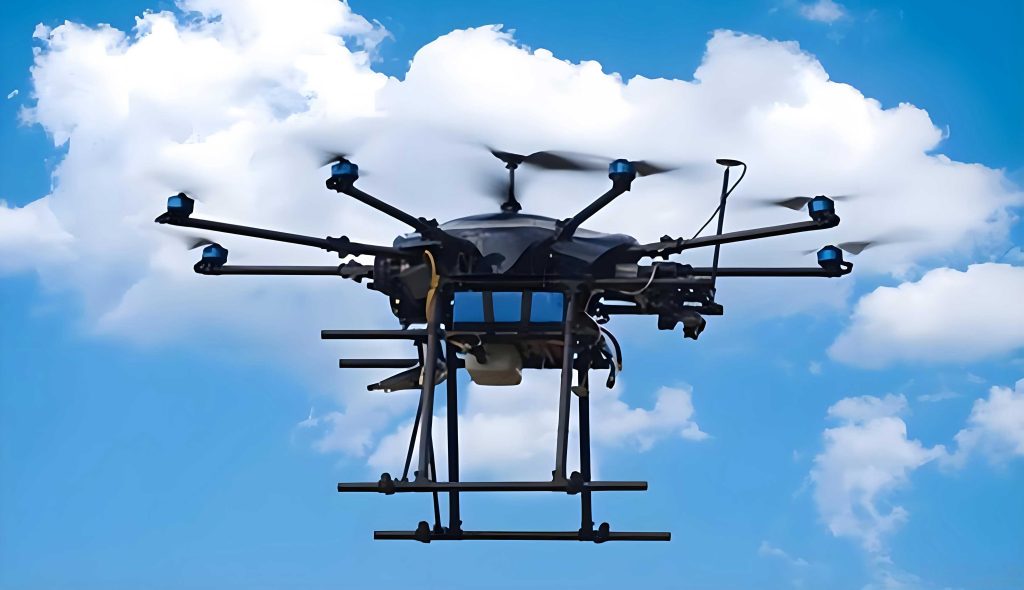
Our system is an integrated solution consisting of three core components: a rotary-wing UAV drone platform, an X-ray inspection unit, and an image acquisition and processing system. The rotary-wing UAV drone serves as an aerial mobile platform with autonomous flight and high-precision hovering capabilities. It carries a high-definition dual-camera system that provides multi-view real-time monitoring for remote operation, ensuring flight safety and positioning accuracy. The UAV drone uses a dedicated winch to suspend the X-ray inspection equipment, allowing dynamic adjustment of suspension length and tension for fine manipulation of the detection position. The X-ray inspection unit comprises an X-ray generator, an imaging plate, a winch assembly, a base, and counterweights. When X-rays penetrate the strain clamp, the attenuated signal is converted into a digital image by the imaging plate. The image is transmitted wirelessly to the ground station, where backend software analyzes it and intelligently identifies and locates crimping defects, achieving precise non-destructive detection.
| Component | Function | Key Parameters |
|---|---|---|
| Rotary-wing UAV drone | Mobile platform for aerial positioning and payload carriage | Max payload: 15 kg; hover accuracy: ±0.1 m; flight endurance: 30 min |
| X-ray generator | Emit penetrating radiation for internal imaging | Voltage: 150 kV; current: 3 mA; focal spot: 0.5 mm |
| Imaging plate (IP) | Capture X-ray shadow into latent image | Resolution: 200 μm; dynamic range: 16 bit |
| Laser scanner & PMT | Read IP and convert to digital signal | Scanning speed: 5 cm/s; quantization: 14 bit |
| Ground control station | Receive data, process images, and display results | Processing unit: GPU-accelerated workstation; bandwidth: 100 Mbps |
UAV Drone Trajectory Planning for Transmission Line Inspection
To achieve accurate and efficient detection of strain clamps, the flight trajectory of the UAV drone must be carefully planned. We adopt a strategy that combines three-dimensional environment modeling with optimization algorithms to ensure that the X-ray inspection equipment remains at the optimal detection position while maintaining flight safety and efficiency. The core of trajectory planning is to generate a collision-free, energy-efficient detection path based on known geographic information of towers and clamps. The detection task is modeled as a path optimization problem in three-dimensional space. Let the positions of the strain clamps be denoted as Pi = (xi, yi, zi) for i = 1, 2, …, n. The ideal detection trajectory is a smooth path passing through the optimal observation points near all Pi.
Path smoothness is critical for both flight stability and image quality. We employ a spline-based planning method where the path is parameterized as:
$$ Q(t) = \sum_{k=0}^{m} C_k B_{k,d}(t) $$
where t is a normalized path parameter (0 ≤ t ≤ 1), Bk,d(t) are B-spline basis functions of degree d, and Ck are control points defining the shape of the path. This formulation guarantees geometric continuity and differentiability throughout the trajectory, avoiding abrupt turns or vibrations that could destabilize the X-ray payload.
After generating the initial path, security constraints are imposed. The UAV drone must maintain a minimum safe distance Dsafe from all transmission line components (conductors, ground wires, tower structures). For any point Q(t) on the path, the distance to the nearest obstacle D(Q(t)) must satisfy:
$$ D(Q(t)) \geq D_{\text{safe}} $$
This constraint is verified in real time using a three-dimensional point cloud of the environment. The final trajectory planning goal is to find a path with the shortest total length or minimal energy consumption. A simplified objective function is:
$$ J = \int_{0}^{1} \left\| \frac{dQ(t)}{dt} \right\|^2 \, dt + \lambda \cdot \max\left(0, D_{\text{safe}} – D(Q(t))\right) $$
where the integral term represents the length of the path (squared norm) and the second term is a penalty function with a positive coefficient λ. By solving this optimization problem, we obtain a safe, efficient, and suitable trajectory for the UAV drone to perform X-ray non-destructive inspection.
| Parameter | Symbol | Typical Value |
|---|---|---|
| Min safe distance to conductors | Dsafe | 2.0 m |
| Spline degree | d | 3 (cubic) |
| Number of control points | m | 10-20 per span |
| Penalty coefficient | λ | 100 |
X-Ray Image Acquisition and Processing
Image acquisition and processing are crucial prerequisites for automatic defect recognition. When the UAV drone hovers at the predetermined detection position, the X-ray generator emits radiation that penetrates the strain clamp. The imaging plate (IP) receives the attenuated signal and forms a latent image. A laser scanner then reads the IP, and a photomultiplier tube converts the latent image into digital electrical signals, generating the raw digital X-ray image. This image is transmitted in real time to the ground control center via a wireless link.
Raw images often suffer from low contrast and noise interference, so preprocessing is required to enhance useful information. First, we apply Gaussian filtering for denoising. The two-dimensional convolution kernel is defined as:
$$ G(x,y) = \frac{1}{2\pi\sigma^2} e^{-\frac{x^2 + y^2}{2\sigma^2}} $$
where (x, y) are pixel coordinates and σ is the standard deviation controlling the smoothing level. This operation effectively suppresses noise but may blur edges. To compensate, we further apply histogram equalization to enhance image contrast by remapping the gray levels so that the output cumulative distribution function approximates a linear function:
$$ s_k = \sum_{j=0}^{k} \frac{n_j}{N} $$
where rk is the k-th input gray level, sk is the transformed output gray level, nj is the number of pixels with gray level j, and N is the total number of pixels in the image. After preprocessing, the internal structures of the crimping tube (aluminum strands, steel core) and potential defects (cracks, voids) become more distinguishable, laying a foundation for subsequent automatic recognition.
| Preprocessing Step | Mathematical Operation | Purpose |
|---|---|---|
| Gaussian filter | $$ G(x,y) = \frac{1}{2\pi\sigma^2} e^{-\frac{x^2+y^2}{2\sigma^2}} $$ | Noise reduction |
| Histogram equalization | $$ s_k = \sum_{j=0}^{k} \frac{n_j}{N} $$ | Contrast enhancement |
| Adaptive thresholding | $$ B(x,y) = \begin{cases} 1 & \text{if } I(x,y) \ge T \\ 0 & \text{otherwise} \end{cases} $$ | Binarization for segmentation |
Defect Detection and Output for Transmission Lines
After preprocessing, the enhanced X-ray image enters the automatic defect recognition and localization stage. Our method combines traditional image processing with machine learning, involving feature extraction, classification, and quantification steps to detect defects such as cracks and voids. First, we use the Canny edge detector to compute the image gradient magnitude, outlining structural contours and extracting suspicious defect regions. The core computation is the gradient magnitude:
$$ |\nabla I| = \sqrt{G_x^2 + G_y^2} $$
where Gx and Gy are the first derivatives of the image along the x and y directions, respectively. Next, threshold segmentation (using e.g., Otsu’s method) converts the gray image into a binary image B(x, y):
$$ B(x,y) = \begin{cases} 1 & \text{if } I(x,y) \ge T \\ 0 & \text{otherwise} \end{cases} $$
where T is the optimal threshold automatically determined by the algorithm. Pixel regions with value 1 are initially classified as foreground (potential defects or high-density structures), thus isolating candidate defect areas.
Second, we quantify features for each region of interest (ROI) to enable classification. These features include geometric and textural descriptors. For example, circularity is used to distinguish linear cracks from blobby voids:
$$ C = \frac{4\pi A}{P^2} $$
where A is the area (in pixels) of the defect region and P is its perimeter. A C value close to 1 indicates a circular shape (e.g., void), while a small value indicates an elongated shape (e.g., crack). Textural features such as contrast are computed from the gray-level co-occurrence matrix:
$$ \text{Con} = \sum_{i,j} (i – j)^2 p(i,j) $$
where i, j are gray levels and p(i,j) is the element of the co-occurrence matrix. A higher contrast value indicates a coarser texture, which helps identify non-uniform gray areas caused by poor crimping.
Finally, the extracted feature vector is input into a pre-trained classifier (e.g., support vector machine, SVM) for final defect type determination. At the same time, the pixel coordinates of the defect region in the image are converted to real-world geographic coordinates using a coordinate transformation model that incorporates the UAV drone’s current GPS position, suspension length, and attitude data. This enables precise geolocation of defects.
| Feature Type | Name | Formula | Physical Meaning |
|---|---|---|---|
| Geometric | Circularity C | $$ C = \frac{4\pi A}{P^2} $$ | Shape compactness (1 for circle) |
| Geometric | Aspect ratio | $$ AR = \frac{L_{\text{major}}}{L_{\text{minor}}} $$ | Elongation measure |
| Textural | Contrast Con | $$ \text{Con} = \sum_{i,j} (i-j)^2 p(i,j) $$ | Local gray variation |
| Textural | Entropy | $$ H = -\sum_{i,j} p(i,j) \log p(i,j) $$ | Degree of randomness |
Field Application Results
To validate the actual performance of our system, we conducted field tests on 500 kV high-voltage transmission lines across multiple provinces. The tests focused on detecting energized strain clamps in service, and we completed inspections on over 200 clamps. In terms of defect identification, the system successfully detected various typical defects including loose crimping, internal cracks, and foreign material inclusions. By comparing results with subsequent outage-based verification (disassembly inspection), we obtained the statistical recognition accuracy presented in the table below.
| Defect Type | Number of Test Samples | Successfully Identified | Recognition Accuracy (%) |
|---|---|---|---|
| Loose/Incomplete Crimping | 85 | 82 | 96.5 |
| Internal Cracks | 42 | 38 | 90.5 |
| Voids | 28 | 26 | 92.9 |
| Foreign Material Inclusions | 15 | 14 | 93.3 |
| Total | 170 | 160 | 94.1 |
The overall comprehensive recognition accuracy reached 94.1%. In terms of detection efficiency, thanks to the mobility of the UAV drone and the automated workflow, the average inspection time per single clamp (including UAV drone flight and positioning, X-ray imaging, image transmission, and automatic analysis) was controlled within 15 minutes. Compared to traditional manual tower climbing detection, our system improves efficiency by more than 70% and eliminates the risk of personnel working at height.
We also compared the performance of our UAV drone-based system with traditional methods in terms of safety, coverage, and accuracy:
| Metric | Traditional Manual Method | Our UAV Drone-Based System |
|---|---|---|
| Safety | High risk of falls and electric shock | No personnel at height, remote operation |
| Inspection per clamp | 45–60 minutes (including climbing, disassembly) | < 15 minutes |
| Defect detection rate | ~70% (visual only, internal defects missed) | 94.1% (internal defects included) |
| Coverage | Requires line outage and de-energization | Energized, no line interruption |
| Data output | Manual notes and photographs | Digital images with geotagged defect locations |
Conclusion
We have successfully developed a non-destructive inspection system for transmission line strain clamps based on UAV drones and X-ray imaging. Field applications demonstrate that this system effectively overcomes the limitations of traditional manual inspection, achieving high-efficiency and high-precision internal defect detection while ensuring operational safety. The specific research outcomes and conclusions are as follows: First, the system achieves an organic integration of the UAV drone mobile platform, X-ray non-destructive detection, and artificial intelligence algorithms, establishing an “air-ground” collaborative inspection framework that innovates the operation and maintenance mode of transmission lines. Second, field test results show that the system’s comprehensive recognition accuracy for internal defects in strain clamps reaches 94.1%, and the inspection time per single clamp is controlled within 15 minutes—significantly superior to traditional methods in both accuracy and efficiency. This work provides a highly practical engineering solution for condition-based maintenance of power transmission infrastructure.