
As a researcher deeply involved in flight control of quadrotor UAV drones, I have spent years exploring how to make these vehicles more stable and precise. The quadrotor UAV drone, widely used in aerial photography, patrol, rescue, and industrial inspection, relies fundamentally on its flight control system. This system determines not only the user experience but also the industrial maturity and high-end application potential of the drone. In this article, I will share my work on designing a Linear Quadratic Regulator (LQR) controller for a quadrotor UAV drone, including the flight dynamics modeling, the cascaded LQR architecture, and simulation validation results.
Technical Background
Compared to traditional helicopters, which have complex mechanical structures and high maintenance costs, and tiltrotor aircraft, which are difficult to maneuver, the quadrotor UAV drone offers a simple structure with four direct-drive rotors. However, the quadrotor is inherently a statically unstable system. It possesses six degrees of freedom yet only four control inputs (the rotor speeds), making it a strongly coupled, underactuated, and nonlinear flight system. External wind disturbances, aerodynamic interactions between rotors, and actuator response delays all degrade flight quality. Therefore, controller design is the core challenge for achieving stable flight of a quadrotor UAV drone.
The Linear Quadratic Regulator (LQR) is one of the most important control methods to address this challenge. By setting weights on state deviations and control effort, LQR finds an optimal balance between stability and energy consumption. It has been widely applied in robotics, automotive control, and flight control. In this work, I focus on an LQR-based control method for quadrotor UAV drones, emphasizing flight dynamics modeling, cascaded LQR controller design, and simulation verification of position, attitude, and angular rate control.
Technical Approach and Process
Flight Dynamics Model of Quadrotor UAV Drone
To design a control “brain” for the drone, we must first understand its motion laws. Establishing the flight dynamics model requires defining motion coordinate systems, which serve as the rules for describing the drone’s position, velocity, attitude, and forces.
I define an inertial coordinate system and a body-fixed coordinate system. The inertial frame originates at the takeoff point, with north, east, and vertical directions forming a right-hand coordinate system. The body frame originates at the center of gravity, with forward, right, and vertical axes forming another right-hand system. For simplicity, I adopt the “flat Earth assumption,” ignoring Earth’s curvature and treating the ground-fixed frame as inertial. The transformation matrix (not expanded here for brevity) maps forces, velocities, and attitudes from the body frame to the inertial frame.
I develop the flight dynamics model for an X-type quadrotor UAV drone, using three basic assumptions: (1) the fuselage is a symmetric rigid body, and as an electric aircraft its mass remains constant during flight; (2) the geometric center coincides with the center of mass; (3) all four motors and rotors have identical parameters, differing only in rotation direction.
The quadrotor controls its position and attitude by varying the four rotor speeds. When all four rotors accelerate together, total thrust increases, primarily affecting vertical motion. Differential thrust between left and right (or front and rear) rotors generates roll (or pitch) moments. Differential thrust between diagonal rotor pairs generates yaw moments.
The total thrust is proportional to the sum of squares of the four rotor speeds. Roll and pitch moments arise from the thrust difference between opposite rotors, while the yaw moment comes from the difference in reaction torques of the two counter-rotating rotor pairs.
Since the quadrotor UAV drone flies at relatively low speeds, I neglect aerodynamic drag forces. The six-degree-of-freedom dynamics model is then governed by gravity, total thrust, three-axis moments, mass, and moments of inertia. The model describes the position changes in the inertial frame and the attitude changes around the body axes.
To facilitate LQR controller design, I linearize the model around the hovering equilibrium point using small-perturbation theory. This means treating the drone as undergoing small attitude and position variations near equilibrium and ignoring higher-order nonlinear terms. In this way, the originally complex nonlinear model becomes a linear state-space model:
$$ \dot{\mathbf{x}} = \mathbf{A} \mathbf{x} + \mathbf{B} \mathbf{u} $$
$$ \mathbf{y} = \mathbf{C} \mathbf{x} $$
where the state vector \(\mathbf{x}\) includes position \((x,y,z)\), velocity \((\dot{x},\dot{y},\dot{z})\), attitude angles \((\phi,\theta,\psi)\), and angular rates \((p,q,r)\). The control input vector \(\mathbf{u}\) comprises total thrust and three-axis control moments \((T, M_x, M_y, M_z)\). The system matrix \(\mathbf{A}\) and control matrix \(\mathbf{B}\) are derived from the linearization. This linear model provides a computable foundation for LQR controller design.
Linear Quadratic Regulator (LQR) Design
With the motion model of the quadrotor UAV drone available, I proceed to design the LQR controller. For a continuous-time linear system, the core idea of LQR is to use state feedback to modify the system’s motion such that state deviations converge quickly while control effort remains moderate. The fundamental LQR control law is:
$$ \mathbf{u} = -\mathbf{K} \mathbf{x} $$
where \(\mathbf{K}\) is the feedback gain matrix computed from the system model and the weight matrices. The controller automatically calculates corrective control inputs based on how far the drone’s current state deviates from the target.
The design involves a cost function that weighs two competing objectives: state deviation cost and control effort cost:
$$ J = \int_{0}^{\infty} \left( \mathbf{x}^T \mathbf{Q} \mathbf{x} + \mathbf{u}^T \mathbf{R} \mathbf{u} \right) dt $$
Here, \(\mathbf{Q}\) is the state weight matrix and \(\mathbf{R}\) is the control weight matrix. Larger weights in \(\mathbf{Q}\) make the controller prioritize faster convergence of position, attitude, or angular rates. Larger weights in \(\mathbf{R}\) make the controller conserve control energy and avoid aggressive actions. The ratio between \(\mathbf{Q}\) and \(\mathbf{R}\) determines whether the quadrotor UAV drone behaves more “agilely” or “smoothly.”
Given the system matrices and weight matrices, the optimal feedback gain \(\mathbf{K}\) is obtained by solving the algebraic Riccati equation:
$$ \mathbf{A}^T \mathbf{P} + \mathbf{P} \mathbf{A} – \mathbf{P} \mathbf{B} \mathbf{R}^{-1} \mathbf{B}^T \mathbf{P} + \mathbf{Q} = 0 $$
$$ \mathbf{K} = \mathbf{R}^{-1} \mathbf{B}^T \mathbf{P} $$
In simple terms, LQR translates flight requirements into weight settings, then computes optimal control gains that balance stability, response speed, and control consumption. This process resembles tuning an intelligent balancing system: we tell it which deviations must be corrected quickly and which control actions should be restrained, and the system calculates a set of optimal control parameters to achieve fast response without excessive oscillation or energy waste.
Key Innovation: Cascaded LQR Controller
The core control architecture of my work is a cascaded LQR controller, consisting of an outer position control loop, an inner attitude control loop, and an innermost angular rate control loop. The outer loop commands the quadrotor UAV drone to reach a target position. The attitude loop translates the position control demand into pitch and roll attitude commands. The angular rate loop rapidly and stably executes the attitude changes.
Specifically, the position loop outputs reference attitude angles to the attitude loop. The attitude loop outputs reference angular rates to the angular rate loop. Finally, the angular rate loop generates the motor speed control commands. This cascaded structure decomposes a complex three-dimensional motion task into multiple hierarchical control problems with distinct response scales.
| Control Loop | Weight Setting Engineering Meaning |
|---|---|
| Position control loop | Primarily constrains x, y, z position deviations and velocity response, enabling the drone to reach the target point smoothly. |
| Attitude control loop | Primarily constrains pitch and roll angle deviations, ensuring fast and not overly overshooting attitude response during horizontal maneuvers. |
| Angular rate control loop | Primarily constrains pitch and roll angular rates, making attitude execution faster and smoother. |
Case Validation and Data: Simulation Analysis
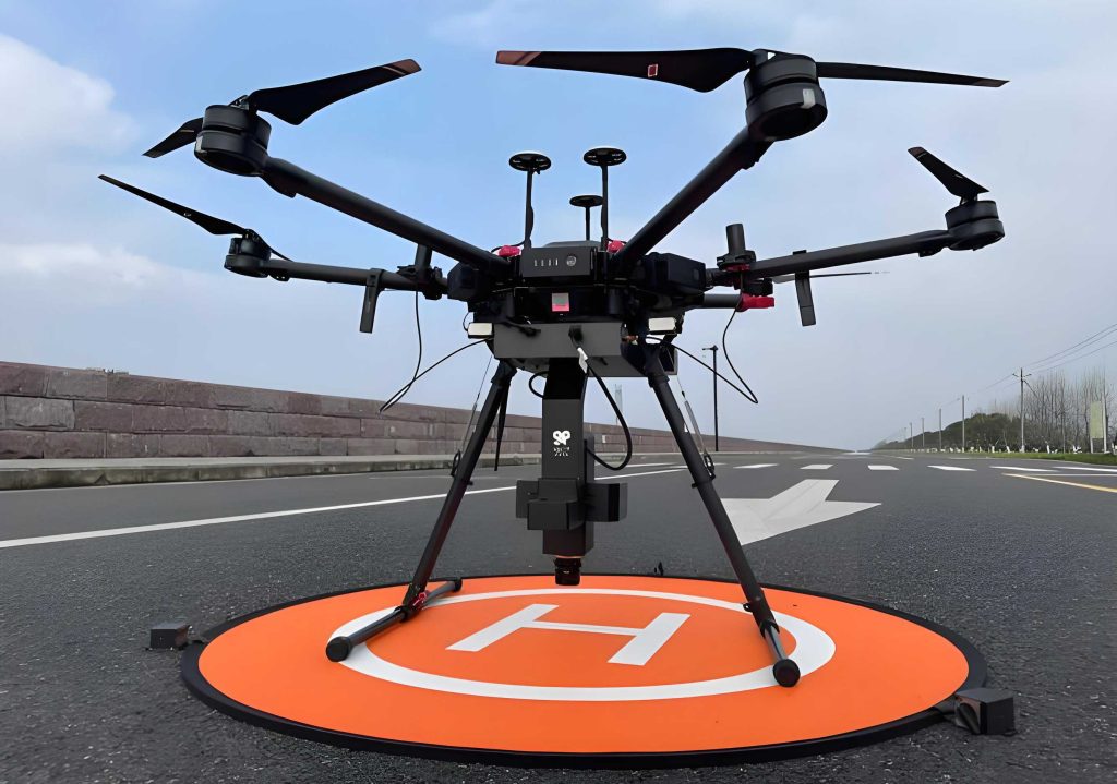
To verify the effectiveness of the LQR controller, I conducted simulation studies on a specific electric quadrotor UAV drone. Key parameters include takeoff weight and moments of inertia. Substituting these parameters into the linearized model yields the state transition matrix \(\mathbf{A}\) and control matrix \(\mathbf{B}\) for controller design.
\(\mathbf{A}\) reflects the intrinsic relationships among position, velocity, attitude, and angular rates. \(\mathbf{B}\) reflects the influence of total thrust and three-axis moments on the state variables. Together they determine the LQR feedback gain calculation.
For the cascaded LQR controller, I designed weight matrices for each loop. The position loop focuses on position deviation and velocity response. The attitude loop focuses on pitch and roll angle tracking. The angular rate loop focuses on the rapidity and smoothness of attitude changes.
During the simulation, I used the commonly adopted “heading-hold” mode: no yaw motion, only pitch and roll to achieve horizontal movement. Therefore, the yaw angle is always assumed to be zero. Considering the limited motor regulation capability, excessive attitude angles may cause insufficient thrust or loss of control, so the attitude target is limited to ±25°.
The overall controller architecture is described as follows: position control, attitude control, and angular rate control pass reference commands sequentially in a cascade, ultimately forming motor control outputs.
For each control loop, the state transition matrix, control matrix, and state variables are defined. In summary, each control loop pays attention only to the most relevant state quantities: the position loop concerns position and velocity; the attitude loop concerns angles and angular rates; the angular rate loop concerns angular rates themselves. This hierarchical modeling reduces the complexity of controller design while maintaining interpretability of the response.
The simulation initial conditions are: the quadrotor UAV drone starts at \([0, 0, -20]\) m (hovering at 20 m altitude). At t = 5 s, it receives a target position command \([100, 100, -50]\) m and begins maneuvering. The drone must climb, move horizontally, decelerate, and finally hover at the target.
From the simulation results (the following descriptions relate to the curves, but without referencing figure numbers): the horizontal position x and y responses show that after receiving the command, the drone completes vertical motion in about 5 s, climbing from 20 m to 50 m altitude. The horizontal motion is completed in about 10 s, reaching the target position. The average horizontal speed is about 15 m/s, and the average vertical speed is about 6 m/s. The horizontal overshoot is less than 5%. Overall, the position control is smooth and accurate, without obvious “overshoot-then-recover” behavior.
The attitude responses (pitch and roll angles) show that during the maneuver, the drone first pitches down and rolls right to accelerate, then pitches up and rolls left to decelerate, finally returning to hover attitude with zero pitch and roll angles. The attitude motion shows no significant overshoot, and the response speed is fast: it takes about 0.7 s to go from –25° to +25°. The maximum attitude angle reaches the ±25° limit, meeting design requirements.
The angular rate responses (pitch rate and roll rate) also show no obvious overshoot, and the tracking performance is good. The tracking time is about 0.2 s. At the start of the maneuver (t = 5 s), due to large position errors, the target angular rates are large. Around t = 10 s, the drone enters the deceleration phase. By t = 15 s, it approaches the hover phase, target values become small, and angular rate tracking becomes smoother.
Combining the results for position, attitude, and angular rates, the cascaded LQR controller enables the quadrotor UAV drone to complete a smooth maneuver from hover to target point, demonstrating good rapidity, stability, and engineering feasibility.
Key numerical data from the simulation is summarized in the table below:
| Metric | Value |
|---|---|
| Vertical motion completion time | ≈ 5 s |
| Horizontal motion completion time | ≈ 10 s |
| Average horizontal speed | ≈ 15 m/s |
| Average vertical speed | ≈ 6 m/s |
| Horizontal position overshoot | < 5% |
| Attitude response time (from –25° to +25°) | ≈ 0.7 s |
| Angular rate tracking time | ≈ 0.2 s |
| Maximum attitude angle | ±25° (limited) |
Value and Impact Analysis
Significance for Ordinary People
This technology can significantly improve the stability and accuracy of quadrotor UAV drones. For ordinary users, the most direct experience is that the drone does not drift easily, the video footage is steadier, and the positioning is more precise. Even in light wind conditions, the drone maintains good flight quality, enhancing applications like aerial photography, pesticide spraying, emergency rescue, and inspection.
Impact on Industry and Society
LQR control technology can drive the upgrading of the UAV drone industry by alleviating the trade-off between control precision, stability, and energy consumption. It improves mission execution efficiency in both military and civilian domains. Furthermore, it stimulates the development of upstream and downstream components such as motors, sensors, flight controller boards, and mission payloads.
Advantages and Challenges
| Category | Content |
|---|---|
| Advantages | High control precision, fast response, balance between stability and control effort; clear structure, easy to implement in engineering; adaptable to different UAV drone parameters. |
| Challenges | Currently mainly validated in simulation; real-world issues such as wind disturbances, sensor noise, and motor delays need further verification; weight matrix tuning requires engineering experience; discrete-time controller implementation still needs improvement. |
Conclusion and Outlook
Through establishing a quadrotor UAV drone flight dynamics model and designing a cascaded LQR controller, I have achieved hierarchical control of position, attitude, and angular rates. Simulation results show that this method enables the quadrotor to perform relatively fast and smooth maneuvers between given target points, with small position overshoot and good attitude and angular rate tracking performance.
In the next 1–3 years, the focus can be on promoting engineering application validation, addressing real-world wind disturbances, sensor noise, motor delays, and discrete system implementation, thereby reducing the debugging cost for industrialization. In the next 5–10 years, further development can include adaptive weight adjustment, disturbance rejection optimization, and AI path planning integration, making LQR control a fundamental building block for autonomous flight capabilities of multirotor UAV drones.
As one of the core control technologies for quadrotor UAV drones, LQR has broad application potential in high-end fields such as precision agriculture, emergency rescue, industrial surveying, and the low-altitude economy.
Q&A
- Can LQR control technology make UAV drones safer?
Yes. It allows the drone to recover more quickly from disturbances like wind, and the attitude angle limit reduces the risk of loss of control. - Is the industrialization threshold for this LQR control technology high?
It is moderate. The core difficulties lie in engineering debugging, discrete system implementation, and parameter adaptation for different drone models. - Can consumer-grade UAV drones use this technology?
Yes. The structure is clear and easy to implement in engineering. When applied to consumer drones, it can improve aerial photography stability and positioning accuracy. - What is the practical difference between LQR-controlled and ordinary drone control?
The most noticeable differences are smoothness and accuracy. The drone’s position response is cleaner, attitude adjustments are smoother, and the drone exhibits less drift during hovering and maneuvering.