
In our study, we focus on the reliability test scheme design for a UAV drone optoelectronic mission payload. Although reliability analysis and FMECA (Failure Mode, Effects, and Criticality Analysis) can evaluate the reliability level of a UAV drone optoelectronic mission payload, both methods emphasize the impact of certain influencing parameters. As a result, they may overlook other factors. Moreover, during the application of these two approaches, the interconnections among various factors are not sufficiently addressed. This leads to inaccuracies in the analysis results. To resolve this situation and enhance the reliability of the analysis, we propose a reliability test scheme for the UAV drone optoelectronic mission payload. This scheme provides a reference for conducting reliability tests and further improves the reliability of the analysis outcomes.
1. Necessity of Reliability Testing for UAV Drone Optoelectronic Mission Payload
Although theoretical reliability analysis and FMECA can comprehensively assess the reliability level of a UAV drone optoelectronic mission payload, they often simplify models by focusing on the effects of certain parameters while ignoring secondary factors. Additionally, the coupling effects among influencing parameters are not considered, and the potential correlations between factors are overlooked. Therefore, conducting real-environment reliability tests on the physical payload is essential. Furthermore, based on field test results of similar optoelectronic mission payloads, many failure modes are caused by complex environmental conditions. Thus, to ensure the reliability of the UAV drone optoelectronic mission payload, we must not only study its reliability under ideal working conditions but also perform physical reliability tests under realistic environments. These tests expose design weaknesses, identify key failure modes, evaluate reliability indices from test data, and propose corresponding improvement measures. This approach enables reliability growth of the UAV drone optoelectronic mission payload and guarantees the overall reliability of the UAV drone system.
2. Design Approach for Reliability Test of UAV Drone Optoelectronic Mission Payload
During mission operations, the UAV drone optoelectronic mission payload is significantly affected by environmental stresses. Basic reliability tests are time-consuming and labor-intensive. To assess the reliability of the payload within a shorter period, we can adopt accelerated life tests. Accelerated life tests are categorized into three types:
- Constant stress accelerated life test: stable method, high accuracy, but long test duration.
- Progressive stress accelerated life test: short test duration, but unstable method and high equipment requirements.
- Step-stress accelerated life test: relatively stable method, simple equipment requirements, shorter test duration compared to constant stress tests, and higher failure rate of test products. Thus, step-stress accelerated life testing has become a new development direction in recent years.
To improve the accuracy of reliability testing for UAV drone optoelectronic mission payloads and effectively shorten the test cycle, many researchers have focused on optimizing step-stress accelerated life test schemes, but results are often unsatisfactory. Therefore, we combine the advantages and disadvantages of the three accelerated life test methods, emphasize step-stress accelerated life testing, design a reasonable step-stress test profile, improve test stability and effectiveness, and achieve the goal of shortening the test cycle while increasing the accuracy of median life estimation at normal stress levels.
3. Step-Stress Accelerated Life Test Method for UAV Drone Optoelectronic Mission Payload
3.1 Reliability Statistical Model for UAV Drone Optoelectronic Mission Payload
Temperature stress is the most critical environmental factor affecting the reliability of a UAV drone optoelectronic mission payload during mission operation. Under temperature stress, the life \( t \) of the payload follows a two-parameter Weibull distribution, with probability density function:
\[
f(t) = \frac{m}{\eta} \left( \frac{t}{\eta} \right)^{m-1} \exp\left[ -\left( \frac{t}{\eta} \right)^m \right], \quad t > 0
\tag{1}
\]
where \( m \) is the shape parameter and \( \eta \) is the scale parameter. Under different temperature conditions, assuming the failure mechanism remains unchanged, the specific reliability statistical model is:
- A1: The shape parameter \( m \) of the Weibull distribution remains constant across different temperature conditions.
- A2: The characteristic life \( \eta \) satisfies the Arrhenius model with respect to environmental temperature.
- A3: Product lifetimes \( t \) are statistically independent and follow a two-parameter Weibull distribution:
\[
\eta = A \exp\left[ \frac{\Delta E}{k(\theta + 273.15)} \right]
\tag{2}
\]
where \( \Delta E \) is the activation energy, \( k \) is Boltzmann’s constant, \( \theta \) is the ambient temperature in °C, and \( A \) is a constant coefficient. Let \( \delta = \ln t \). Then the Weibull distribution transforms into an extreme value distribution with probability density function:
\[
f(\delta) = \frac{1}{\sigma} \exp\left( \frac{\delta – \mu}{\sigma} \right) \exp\left[ -\exp\left( \frac{\delta – \mu}{\sigma} \right) \right]
\tag{3}
\]
where \( \mu = \ln \eta \) and \( \sigma = 1/m \). The above model becomes a linear-extreme value statistical model:
- B1: The distribution parameter \( \sigma \) remains constant under different temperature stress levels.
- B2: The distribution parameter \( \mu \) is a function of stress \( x \).
- B3: The log-lifetime \( \delta \) is statistically independent and follows an extreme value distribution:
\[
\ln \eta = \mu(x) = \gamma_0 + \gamma_1 x
\tag{4}
\]
where \( x = 1000 / (\theta + 273.15) \), \( \gamma_0 = \ln A \), and \( \gamma_1 = \Delta E / (1000k) \).
3.2 Basic Principle of Step-Stress Accelerated Life Test
In the step-stress accelerated life test, the stress parameter is expressed using temperature conversion parameter \( x \). When the test stress parameter is \( x_q \) (except \( q=1 \)), to obtain complete test life data under \( x_q \), we use a time conversion method that accounts for the cumulative test time under all previous stress parameters. This compensates for the effect of earlier stress levels on product life. To evaluate the reliability of the UAV drone optoelectronic mission payload during operation, we select temperature \( \theta \) as the accelerated stress for the step-stress test. Based on the reliability statistical model A1, the cumulative distribution function of the Weibull distribution gives:
\[
1 – \exp\left[ -\left( \frac{t_q}{\eta_q} \right)^{m_q} \right] = 1 – \exp\left[ -\left( \frac{t_j}{\eta_j} \right)^{m_j} \right]
\tag{5}
\]
From A2, \( m_q = m_j \), so:
\[
\frac{t_q}{\eta_q} = \frac{t_j}{\eta_j}
\tag{6}
\]
Using B3 and Eq. (4), we obtain:
\[
t_q = \exp\left[ \gamma_1 (x_q – x_j) \right] t_j
\tag{7}
\]
For multiple sample step-stress accelerated life testing, suppose there are \( n \) test products, \( K \) stress levels with values \( x_1 > x_2 > \cdots > x_K \), conversion periods \( \tau_1, \tau_2, \ldots, \tau_K \), and failure counts \( r_1, r_2, \ldots, r_K \). The failure time of a product is calculated starting from the beginning of each stress level. If a product fails during the test period \( t_q \) under stress \( x_q \), then the test time under previous \( q-1 \) stress levels is converted to an equivalent time under \( x_q \). The true life of the product under stress \( x_q \) is:
\[
t_{iq} = \tau_q + \sum_{j=1}^{q-1} \tau_j \exp\left[ \gamma_1 (x_q – x_j) \right]
\tag{8}
\]
After conversion, all failure data under different stress levels can be transformed to equivalent failure times under the highest stress level \( x_1 \). For example, the equivalent life of a product that fails under stress \( x_i \) is:
\[
t_{i}^{\star} = \sum_{j=1}^{i-1} \tau_j \exp\left[ \gamma_1 (x_1 – x_j) \right] + \tau_i
\tag{9}
\]
These transformed data can then be used for statistical inference.
3.3 Optimization Criterion for Step-Stress Accelerated Life Test of UAV Drone Optoelectronic Mission Payload
Based on the reliability statistical model, we assume the following conditions to optimize the step-stress test plan:
- (1) The total test has a fixed censoring time \( \tau_S = \tau_1 + \tau_2 + \cdots + \tau_K \). The test continues until either the product fails or the total time is reached.
- (2) At each transition from stress \( x_i \) to \( x_{i+1} \) (with conversion period \( \tau_i \)), failed products are removed, and surviving products continue.
- (3) Before the test starts, the normal stress parameter \( x_0 \) and the maximum stress parameter \( x_K \) are set. (The maximum temperature stress must ensure that the failure mechanism does not change.)
The optimization objective is to minimize the asymptotic variance of the maximum likelihood estimator of the median life under normal stress, or equivalently, to maximize the precision of reliability estimation. The design variables include the number of stress levels \( K \), the stress values \( x_i \), and the conversion periods \( \tau_i \).
3.4 Determination of Step-Stress Accelerated Life Test Parameters
3.4.1 Normal Test Temperature
According to GJB150A, the operating temperature range of a UAV drone optoelectronic mission payload is -55°C to 65°C. Considering that the test chamber is a closed, constant-temperature, constant-humidity space and referencing environmental test data of similar optoelectronic payloads, we set the ambient temperature to \( \theta_0 = 20^\circ\mathrm{C} \).
3.4.2 Maximum Temperature
The choice of the maximum test temperature must first avoid destructive testing. Under this premise, the temperature should be chosen as the maximum within the feasible range. According to the working environment of the UAV drone optoelectronic mission payload, we set the highest temperature at 70°C and the lowest at -60°C.
3.4.3 Total Censoring Time Upper Limit \( \tau_S \)
We select step-stress accelerated life testing because its total censoring time is shorter than that of constant stress tests. For similar UAV drone optoelectronic mission payloads, the total censoring time upper limit for constant stress tests is 600 hours. Considering test acceleration and budget, we set the total censoring time upper limit for this test to \( \tau_S = 240 \) hours.
3.4.4 Step-Stress Parameters
The test is divided into a low-temperature stress phase and a high-temperature stress phase. We start from the low-temperature phase. The initial temperature is set to 20°C (normal test temperature). According to GJB150A, the cooling rate is 2°C/min, and the heating rate is also 2°C/min. The temperature is decreased (or increased) in steps of 10°C. After each step, the temperature is stabilized and held for 30 minutes, during which functional tests are performed. This continues until the product fails, indicating the operational or destruction limit.
The following table summarizes the test temperature parameters:
| Phase | Step | Temperature (°C) | Stress Parameter \( x = 1000/(\theta+273) \) | Hold Time (min) |
|---|---|---|---|---|
| Low-Temperature | 1 | 20 | 3.413 | 30 |
| 2 | 10 | 3.533 | 30 | |
| 3 | 0 | 3.663 | 30 | |
| 4 | -10 | 3.802 | 30 | |
| 5 | -20 | 3.952 | 30 | |
| … | … | … | … | |
| High-Temperature | 1 | 30 | 3.300 | 30 |
| 2 | 40 | 3.195 | 30 | |
| 3 | 50 | 3.096 | 30 | |
| 4 | 60 | 3.003 | 30 | |
| 5 | 70 | 2.915 | 30 |
4. Step-Stress Accelerated Life Test Procedure for UAV Drone Optoelectronic Mission Payload
4.1 Test Equipment
We use an American Environmental Simulation three-in-one test chamber (model: Sanhe). It features multi-channel data monitoring and testing systems, capable of applying high/low temperature and humidity combined environmental stresses. This allows comprehensive reliability testing of the UAV drone optoelectronic mission payload under combined environments. The chamber dimensions are 3000 mm × 2300 mm × 2500 mm (length × width × height), with a working volume of 3 m³ and a temperature range of -70°C to +100°C.
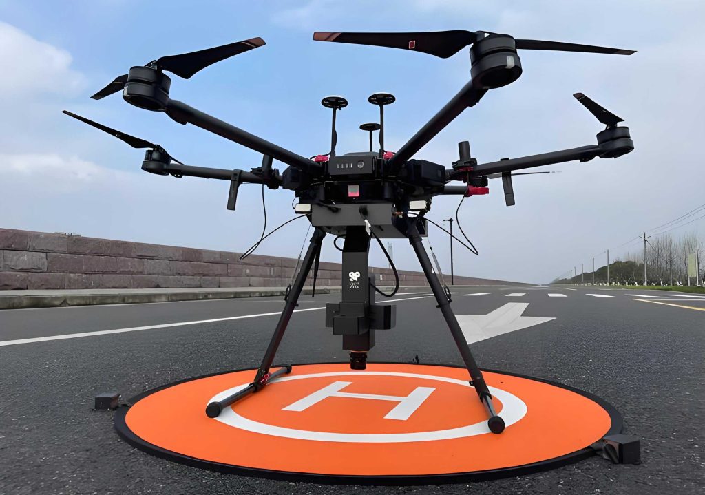
The chamber is equipped with a programmable controller and a data acquisition system that records temperature, humidity, and product status in real time.
4.2 Test Procedure
According to the test plan, the procedure is as follows:
- Low-temperature phase: Set the initial temperature to 20°C. Start the low-temperature step-stress phase. For each step, reduce the temperature by 10°C at a rate of 2°C/min. After the temperature stabilizes, hold for 30 minutes and perform functional tests on the UAV drone optoelectronic mission payload. If the product passes, proceed to the next lower temperature step. Continue until a failure occurs, which indicates the low-temperature operational limit or destruction limit.
- High-temperature phase: Set the initial temperature back to 20°C (or start from the last non-failure low temperature). Increase the temperature by 10°C at 2°C/min for each step. After stabilization, hold for 30 minutes and perform functional tests. Continue until failure occurs, indicating the high-temperature operational limit or destruction limit.
During the test, if any failure occurs, the test chamber operator shall record the failure mode and time in the test report.
4.3 Monitoring Parameters
Based on the failure mode analysis, the following parameters are selected for inspection and measurement during the test:
| No. | Parameter | Description |
|---|---|---|
| 1 | Mechanical motion | Check for jamming or abnormal movement in the gimbal and other moving parts of the UAV drone optoelectronic mission payload. |
| 2 | Optical sensor status | Detect whether each optical sensor (e.g., visible camera, infrared camera, laser rangefinder) functions correctly, including image quality, signal output, and communication. |
| 3 | Wear of components | After long-term cycling, inspect the wear condition of bearings, gears, and other mechanical components. |
| 4 | Electrical continuity | Monitor cable connections, power supply stability, and signal transmission integrity. |
| 5 | Thermal imaging performance | For infrared sensors, check the uniformity and accuracy of temperature measurement. |
All measurements are recorded at each temperature step after the 30-minute hold period. If any parameter exceeds the specification limits, a failure is declared.
5. Conclusion
In this paper, we have designed a comprehensive reliability test scheme for a UAV drone optoelectronic mission payload. First, we demonstrated the necessity of conducting physical reliability tests under realistic environmental conditions by analyzing the severity of the actual working environment and the results of previous field tests. Second, considering the environmental stresses experienced by the UAV drone optoelectronic mission payload and available test facilities, we developed a step-stress accelerated life test plan. The plan includes a detailed statistical model based on the Weibull distribution and the Arrhenius model, a time conversion method to handle cumulative stress effects, and an optimization criterion to improve estimation precision. The test parameters—normal temperature, maximum temperature, total censoring time, and step increments—are determined according to military standards and practical considerations. The test procedure, equipment, and monitoring parameters are specified to ensure the test can reveal weaknesses and collect reliable data. This scheme effectively overcomes the limitations of pure theoretical analysis (reliability analysis and FMECA) by considering factor interactions and real-environment effects. It provides a valuable reference for reliability growth and evaluation of UAV drone optoelectronic mission payloads, ultimately enhancing the overall reliability of the UAV drone system.