
The rapid advancement of unmanned aerial vehicle (UAV) technology has led to the widespread adoption of fixed-wing UAVs in both military and civilian applications, owing to their advantages of low cost, low risk, and high operational efficiency. As a critical component for flight attitude control, the rudder surface performance directly affects flight safety and mission completion. Traditional fixed-wing UAVs typically employ rigid hinge structures for their control surfaces, aligning with the classical theory of rigid body rotation. However, to enhance aerodynamic efficiency, modern aerodynamic designs have increasingly replaced these rigid hinges with flexible hinge sheets. This novel structure introduces a complex compound motion characteristic for the rudder surface, combining rotations around multiple axes with minute displacements, which deviates from the simple single-axis rotation. This complexity renders conventional detection methods—such as encoders and inclination sensors—ineffective for accurately measuring the actual deflection angle of these flexible hinge rudder surfaces. To solve this critical problem, our team has designed a comprehensive automated testing system based on a three-axis digital gyro angle meter, specifically tailored for the unique characteristics of the flexible hinge rudder surface on a fixed-wing UAV.
1. System Architecture and Working Principle
The core working principle of our proposed system is illustrated by the integration of a high-precision three-axis digital gyro angle meter with a test computer built on PXIe bus technology. The system architecture is designed to be highly automated and intelligent. The test computer serves as the central control and processing unit. It commands a dedicated power module to supply a stable DC 12 V power source to the three-axis digital gyro angle meter, ensuring its optimal operating condition. A CAN bus module acts as the primary communication and control interface. Under the predefined control logic of the test software, this module generates precise commands to control the UAV’s rudder actuators, commanding the rudder surfaces to move to specific target angles. While the rudder surface moves, the three-axis digital gyro angle meter continuously captures its real-time angular deflection data. This raw data is then transmitted back to the test computer via a high-speed RS422 serial bus. The test computer’s software processes the received data, compares it against predefined standard parameters, calculates errors, and performs a comprehensive performance evaluation. Ultimately, the system generates a detailed test report, providing a definitive assessment of the rudder surface’s functionality and accuracy.
2. Hardware Platform Design
The hardware platform is meticulously designed to ensure stability, accuracy, and robustness in demanding operational environments.
2.1 Test Computer
The test computer is a custom-built system based on the PXIe bus architecture. Its key hardware modules are as follows:
- Chassis and Backplane: The system uses a PXIC-7911 chassis, which integrates a display, mouse, keyboard, and internal power supply, enhancing portability and ease of use. Its ruggedized design allows it to operate reliably in a temperature range of -20°C to +50°C, making it suitable for harsh field conditions. The PXIe-BP3309 backplane provides one system slot, six PXIe hybrid peripheral slots, and one PXI slot, offering abundant interface resources for future expansion. It supports hot-swapping, significantly improving maintenance efficiency.
- Processor Module: A PXIe-76F2 CPU module, featuring an Intel Core i7 1.9 GHz processor, 8 GB of RAM, and a 500 GB hard drive, handles all data processing and storage tasks with high efficiency.
- Communication Modules: A PXIe6210 serial module, with 16 RS-422 channels, is used for high-speed, stable communication with the gyro angle meter. The differential signal transmission method effectively suppresses electromagnetic interference. A PXI4002A CAN module, with 2 CAN channels supporting baud rates from 5 kbps to 1 Mbps, precisely controls the UAV’s rudder actuators. It also features fault diagnosis capabilities to monitor bus status.
- Power Module: A custom power module provides a stable and low-ripple DC 12 V output for the angle meter, incorporating overcurrent and overvoltage protection circuits for safety.
2.2 Rudder Surface Detection Unit
The detection unit is composed of the core sensor and a mechanical fixture. The ML7100-MEMS three-axis digital gyro angle meter is the heart of this unit. It incorporates a high-performance digital signal processing chip and adaptive filtering technology to overcome zero-point drift issues. Furthermore, a temperature compensation algorithm ensures high-precision measurements (<0.01° resolution) across a wide temperature range of -40°C to +85°C. The fast-installation fixture is custom-designed for specific rudder surface geometries. It ensures quick and rigid attachment of the sensor, with a guaranteed perpendicular orientation between the sensor’s measurement axis and the rudder surface’s hinge axis, which is critical for accurate angle measurement.
3. Software Design
The test software is developed on the LabWindows/CVI platform and runs on a Windows 10 operating system. It adopts a modular design philosophy with four main functional modules: user management, system self-test, rudder surface testing, and report generation.
3.1 Software Functionality
- User Management Module: Manages operator accounts, logins, and permission assignments. It uses encrypted password storage and role-based access control to ensure system operational security.
- System Self-test Module: Automatically checks internal communication links, the CAN module initialization status, and other critical system health parameters upon startup. Any detected faults trigger an alarm and generate a detailed report for rapid troubleshooting.
- Rudder Surface Testing Module: This is the core testing engine, providing both manual and automatic test modes. In the manual mode, an operator can select a specific rudder surface for targeted diagnosis. The automatic mode loads a pre-configured test strategy and uses multi-threading to execute tests on all rudder surfaces in parallel without human intervention, significantly boosting efficiency. The detailed test flow for the manual mode is presented in the following pseudo-code table.
- Report Generation Module: Automatically generates standardized test reports in PDF or Excel format. The report includes the UAV model, serial number, rudder surface type, measurement data, pass/fail criteria, and a final conclusion. This module supports custom templates to meet specific enterprise requirements.
| Step | Action |
|---|---|
| 1 | Start and perform system self-test. If failed, report error. |
| 2 | Select test mode. |
| 3 | If auto mode, load detection strategy. |
| 4 | Command the specific rudder surface to its mechanical zero position. |
| 5 | Initialize the digital gyro angle meter and reset its zero point. |
| 6 | For the selected rudder (e.g., left rudder), proceed with manual test. |
| 7 | Command the rudder to a series of target angles (e.g., -20°, -15°… 20°). |
| 8 | At each target position, read the actual deflection angle from the gyro meter. |
| 9 | Compare the measured angle with the set value and perform pass/fail judgement. |
| 10 | If all tests are complete, generate the test report; otherwise, return to step 7 for the next target angle. |
3.2 Rudder Surface Deflection Angle Calculation
The three-axis digital gyro angle meter is based on MEMS technology. It contains three orthogonal gyroscopic sensors that measure angular velocity \(\omega(t)\) around the x, y, and z axes. The operation is based on the Coriolis effect, where a vibrating mass experiences a Coriolis acceleration when the sensor rotates, which is then converted into a voltage signal \(V(t)\). The relationship between the output voltage and the angular velocity is linear:
$$V(t) = k \cdot \omega(t)$$
where \(k\) is the sensitivity coefficient of the sensor. To obtain the absolute deflection angle \(\theta(t)\), the angular velocity is integrated over time:
$$\theta(t) = \int_{0}^{t} \omega(\tau) d\tau = \int_{0}^{t} \frac{V(\tau)}{k} d\tau$$
In the software implementation, a discrete numerical integration method is used for real-time calculation. At the \(n\)-th sampling instant, with a fixed sampling interval \(\Delta t\), the angle is updated as:
$$\theta_{n+1} = \theta_n + \omega_n \cdot \Delta t$$
This recursive formula allows for the dynamic calculation of the spatial deflection angle.
4. Engineering Application and Calibration
The system’s accuracy was rigorously calibrated using a high-precision three-axis turntable. The results demonstrated an outstanding performance, with a measurement accuracy superior to 0.05° for both the rudder and elevator surfaces. This high accuracy is essential for detecting subtle deviations in the flexible hinge movement.
A critical aspect of the engineering application is the installation of the fast fixture. It is imperative to ensure that the fixture is perfectly perpendicular to the rudder surface’s hinge axis. Any misalignment introduces a systematic error that will directly affect the test results. Calibration procedures include a zero-point alignment step where the sensor is initialized after the rudder surface is commanded to its mechanical zero position.
Upon successful installation, the operator can use the test software’s intuitive graphical user interface. After selecting the appropriate test item and clicking the “Start Detection” button, the entire test sequence runs automatically. This hands-free operation dramatically improves throughput.
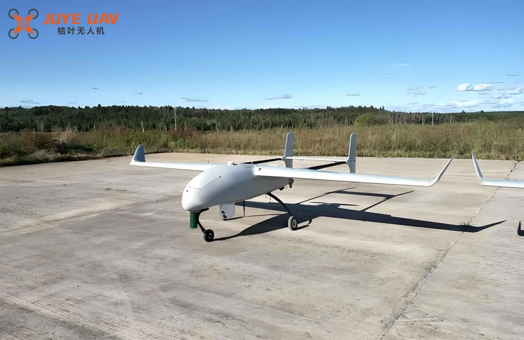
The system was successfully deployed in the production and pre-flight inspection phases for a specific model of fixed-wing UAV. It has completed test tasks for multiple batches of UAVs. A summary of the test results from one batch for the left rudder surface is provided in Table 2. The test results show a high degree of agreement between the measured values and the commanded setpoints for aircraft 1, aircraft 8, and aircraft 13. The maximum deviation observed was 0.02° for aircraft 13 at the 20.00° setpoint. This data fully validates the system’s reliability and accuracy, providing a strong guarantee for the UAV’s flight safety. Compared to traditional manual methods, this automated system reduces the testing time for a single fixed-wing UAV from 30 minutes to 10 minutes, achieving a 66.7% improvement in test efficiency.
| Commanded Angle (°) | Measured Angle (Aircraft 1) (°) | Measured Angle (Aircraft 8) (°) | Measured Angle (Aircraft 13) (°) | Lower Limit (°) | Upper Limit (°) |
|---|---|---|---|---|---|
| -20.00 | -19.98 | -20.01 | -19.99 | -20.05 | -19.95 |
| -15.00 | -14.99 | -15.00 | -14.98 | -15.05 | -14.95 |
| -10.00 | -10.02 | -9.99 | -10.01 | -10.05 | -9.95 |
| -5.00 | -5.01 | -5.00 | -4.99 | -5.05 | -4.95 |
| 0.00 | 0.01 | 0.00 | 0.01 | -0.05 | 0.05 |
| 5.00 | 5.00 | 5.01 | 4.99 | 4.95 | 5.05 |
| 10.00 | 9.99 | 10.01 | 10.00 | 9.95 | 10.05 |
| 15.00 | 14.98 | 15.02 | 15.00 | 14.95 | 15.05 |
| 20.00 | 19.99 | 20.02 | 20.02 | 19.95 | 20.05 |
5. Performance Analysis and Error Budget
The complete error budget for the testing system is a composite of several factors. The primary contributors are:
- Sensor Accuracy: The ML7100-MEMS sensor has a specified non-linearity and zero-point stability. Over a temperature range of -40°C to +85°C, the combined effect is maintained within \(\pm0.02^\circ\). The digital filtering and temperature compensation algorithms are crucial for this level of performance.
- Installation Error: This is the most significant potential source of systematic error. A misalignment \(\phi\) between the sensor axis and the hinge axis causes a cosine error. The measured angle \(\theta_{meas}\) is related to the true angle \(\theta_{true}\) by \(\theta_{meas} = \theta_{true} \cos(\phi)\). For a small misalignment of 1°, the error is approximately 0.015%. The custom fixture is designed with tight tolerances ( \(\pm0.1^\circ\) ) to minimize this.
- A/D Conversion and Quantization Error: The internal analog-to-digital converter (ADC) in the sensor has a resolution of 0.01°, contributing a quantization error of \(\pm0.005^\circ\).
- Transmission Error: The RS422 serial communication is a digital protocol with error detection (e.g., parity checks). The bit error rate (BER) is extremely low (< 10^{-12}), making transmission errors negligible.
The overall combined standard uncertainty \(u_c\) can be calculated by root-sum-square (RSS) of the individual uncertainty components. Using the values above, the RSS uncertainty is:
$$u_c = \sqrt{(0.02^\circ)^2 + (0.015^\circ)^2 + (0.005^\circ)^2} \approx 0.026^\circ$$
This theoretical analysis aligns well with the empirical calibration result of 0.05° (which includes additional safety margins and environmental factors not modeled here). This high accuracy is now a benchmark for testing flexible hinge rudders on fixed-wing UAVs.
6. Comparison with Traditional Methods
Traditional methods for measuring rudder surface deflection angles predominantly relied on mechanical protractors or single-axis inclinometers. For fixed-wing UAVs with rigid hinges, these methods were adequate. However, for the modern flexible hinge design, these methods fail to deliver acceptable accuracy. The primary limitations of traditional methods are:
- Inability to Handle Compound Motion: A single-axis sensor is blind to rotations around other axes or translational components of the rudder’s motion. This leads to reading an apparent angle that is a composite of all motions, not the true deflection.
- Contact and Fixturing Issues: Mechanical protractors require physical contact and alignment, which is difficult to standardize and introduces human error. They are also slower and more labor-intensive.
- Low Throughput: Manual reading and recording are time-consuming, reducing the overall testing throughput for a production line.
The proposed system overcomes all these limitations. The three-axis gyro meter provides a true three-dimensional measurement of the rudder’s orientation. The fast-installation fixture and automated software reduce operator dependency and dramatically increase speed. The 66.7% increase in testing efficiency directly translates to cost savings and faster turnaround times for manufacturing and pre-flight checks of fixed-wing UAV fleets.
7. Conclusion
In response to the unique challenge of accurately testing the deflection angles of flexible hinge rudder surfaces on modern fixed-wing UAVs, we have successfully designed and implemented a comprehensive automated test system. The system leverages a high-precision three-axis MEMS digital gyro angle meter as its core sensing element, combined with a robust PXIe-based test computer and intelligent software developed in the LabWindows/CVI environment. Through a rigorous calibration process, the system achieves a measurement accuracy superior to 0.05°, which was verified on a high-precision turntable. In extensive engineering applications across multiple production batches of a specific fixed-wing UAV model, the system has proven its stability, reliability, and user-friendliness. It has not only solved the critical problem of measuring angles on flexible hinge surfaces—a task impossible for traditional methods—but also boosted the testing efficiency by an impressive 66.7%, reducing the total test time per aircraft from 30 to 10 minutes. This system has become an indispensable tool for quality control during the production and pre-flight inspection of this fixed-wing UAV platform. Its success demonstrates a significant advancement in the field of UAV testing and measurement, setting a new standard for ensuring the flight safety and mission capability of fixed-wing UAVs equipped with advanced aerodynamic control surfaces.