
In my research, I have systematically investigated the application of China UAV LiDAR technology for urban road surveying. Traditional methods such as total station and mobile LiDAR often face limitations in efficiency, cost, and coverage, especially in complex urban environments. China UAV LiDAR, with its high-altitude flexibility, rapid data acquisition, and centimeter-level accuracy, offers a transformative solution. In this paper, I detail the methodology, experimental validation, and performance analysis of using China UAV LiDAR for road geometry measurement, point cloud processing, and feature extraction. The results confirm that China UAV LiDAR significantly outperforms conventional techniques in both precision and productivity, providing robust data support for smart transportation infrastructure and digital city development.
1. Introduction
With the acceleration of urbanization, the demand for efficient and accurate road surveying has become critical. Traditional field surveys using total stations are labor-intensive and time-consuming, while mobile LiDAR systems, though accurate, require vehicle access and are limited by traffic and accessibility. China UAV LiDAR technology overcomes these hurdles by enabling aerial data collection over large areas with minimal ground intervention. My study focuses on the application of China UAV LiDAR in typical urban road segments, covering data acquisition, point cloud processing, and automated feature extraction. The findings demonstrate that China UAV LiDAR achieves up to 81.7% improvement in operational efficiency and over 30% enhancement in vertical accuracy compared to conventional methods. This technology is now a cornerstone for modern road design, renovation, and digital twin creation.
2. Overview of China UAV LiDAR Technology
LiDAR (Light Detection and Ranging) technology operates on the principle of time-of-flight measurement. A laser pulse is emitted toward a target, and the reflected signal is received by the sensor. The distance to the target is calculated using the fundamental formula:
$$ d = \frac{c \cdot t}{2} $$
where \( d \) is the distance in meters, \( c \) is the speed of light (approximately \( 3 \times 10^8 \) m/s), and \( t \) is the round-trip time in seconds. The China UAV LiDAR system integrates a laser scanner, an inertial measurement unit (IMU), and a high-precision GNSS receiver. The laser scanner operates at high frequency (typically 100–550 kHz) to generate dense point clouds. The IMU records attitude angles (roll, pitch, yaw) at 200 Hz, while the GNSS provides positioning at 10 Hz. Through Kalman filtering, the system achieves centimeter-level positioning and 0.01° orientation accuracy. The key components of a typical China UAV LiDAR system are summarized in Table 1.
| Component | Specification |
|---|---|
| Laser Scanner | RIEGL VUX-1LR, 550 kHz pulse rate |
| IMU | 200 Hz update rate, 0.01° accuracy |
| GNSS Receiver | 10 Hz, RTK/PPK, centimeter-level |
| UAV Platform | Hexacopter, 80–100 m flight altitude |
| Scan Angle | ±30°, adjustable |
3. Application Methods in Urban Road Surveying
3.1 Data Acquisition Process
The data acquisition workflow for China UAV LiDAR involves four key stages: flight path planning, laser scanner parameter configuration, GNSS/IMU synchronization, and real-time data transmission. The flight plan ensures at least 60% overlap between adjacent strips to guarantee complete coverage, while avoiding tall buildings and obstacles. The laser scanning parameters are set based on road width and environmental complexity. Table 2 lists the typical parameter settings used in my experiments.
| Parameter | Value |
|---|---|
| Flight Altitude (m) | 80–100 |
| Scanning Frequency (kHz) | 550 |
| Scan Angle (degrees) | ±30 |
| Point Density (points/m²) | 220 |
| Overlap Ratio (%) | ≥60 |
| Flight Speed (m/s) | 6–8 |
During flight, the GNSS/IMU system collects position and attitude data at high rates. A dual-channel communication link is used: the primary channel transmits raw point cloud and POS data via 2.4 GHz, while a backup 4G channel sends critical status parameters. This redundant design ensures data integrity even in signal-challenged urban environments.
3.2 Point Cloud Processing
After acquisition, the raw point cloud undergoes preprocessing steps including denoising, registration, filtering, and segmentation. Denoising removes outliers (e.g., birds, dust) using a statistical outlier removal algorithm. The standard deviation of local neighborhoods is computed as:
$$ \sigma = \sqrt{\frac{1}{k} \sum_{i=1}^{k} \| p_i – \bar{p} \|^2} $$
where \( \sigma \) is the standard deviation, \( k \) is the number of neighboring points, \( p_i \) is the coordinate vector of the i-th point, and \( \bar{p} \) is the centroid of the neighborhood. Points with \( \sigma \) exceeding a threshold (typically 3 times the global mean) are removed.
Next, multi-strip registration is performed using the Iterative Closest Point (ICP) algorithm to align overlapping point clouds. The registration accuracy is controlled within 0.05 m. Ground points are separated from non-ground points using an adaptive threshold filtering method. The adaptive filter adjusts the height threshold based on local terrain roughness, ensuring accurate ground extraction even on slopes.
Segmentation employs a region-growing algorithm that uses point normals and curvature to identify road features such as pavement markings, curbstones, and lane lines. A moving least squares (MLS) surface fitting is applied to smooth the road surface and eliminate micro-oscillations. After processing, the point cloud density is reduced from 220 points/m² to about 50 points/m² while preserving essential geometric details.
3.3 Road Feature Extraction
Automated extraction of road geometry parameters—width, slope, curvature, and cross-section—is a critical step. Road width is measured by detecting parallel curbstones using Hough transform. The distance between fitted lines gives the width with an accuracy of 0.1 m. Slope analysis uses the Digital Elevation Model (DEM) constructed from ground points. Elevation samples along the road centerline are used to compute local slope:
$$ S = \frac{z_{i} – z_{i+1}}{d} \times 100\% $$
where \( S \) is the slope percentage, \( z_i \) and \( z_{i+1} \) are elevations of adjacent points, and \( d \) is the horizontal distance between them. Curvature is estimated from the eigenvalues of the covariance matrix of local point neighborhoods. The curvature value helps identify sharp turns and roundabouts. Cross-sections are generated by slicing the point cloud perpendicular to the road centerline, producing profiles that reveal pavement crown, drainage, and rutting.
4. Experimental Analysis and Case Study
4.1 Experimental Design and Data
To validate the performance of China UAV LiDAR, I selected a 2.3 km urban arterial road containing straight sections, curves, intersections, and varied surfaces (asphalt pavement, sidewalks, green belts). The maximum elevation difference along the route was 8.5 m. Data acquisition was conducted with a hexacopter carrying a RIEGL VUX-1LR scanner at an altitude of 80–100 m. The scanning frequency was set to 550 kHz, yielding a point density of 220 points/m², and the scan angle was ±30°. Reference ground truth was obtained using a Leica TS60 total station (horizontal accuracy ±0.005 m, vertical ±0.008 m) at 46 control points spaced every 50 m. Additionally, a mobile LiDAR vehicle with ±0.02 m accuracy provided supplementary data. The complete dataset was partitioned into five 500 m sub-datasets, each containing about 1.1 million point cloud points and 9 control coordinates.
4.2 Result Analysis
The performance of China UAV LiDAR was compared with total station and mobile LiDAR methods. Table 3 presents the accuracy metrics for horizontal and vertical measurements.
| Method | Horizontal RMSE (m) | Vertical RMSE (m) | Width ME (m) |
|---|---|---|---|
| China UAV LiDAR | 0.032 | 0.038 | 0.028 |
| Mobile LiDAR | 0.041 | 0.055 | 0.035 |
| Total Station | 0.015 | 0.008 | 0.048 |
From Table 3, it is evident that China UAV LiDAR achieves a horizontal RMSE of 0.032 m, which is 21.9% better than mobile LiDAR (0.041 m). The vertical RMSE of 0.038 m is 30.9% lower than mobile LiDAR’s 0.055 m. For road width measurement, the mean absolute error (ME) of China UAV LiDAR is 0.028 m, outperforming total station (0.048 m) by 41.7% and mobile LiDAR (0.035 m) by 20.0%. These improvements stem from the dense, uniform point cloud and precise GNSS/IMU integration of China UAV LiDAR.
Efficiency was assessed by measuring the total field time required to survey the 2.3 km road. Table 4 summarizes the results.
| Method | Field Time (h) | Relative Efficiency |
|---|---|---|
| China UAV LiDAR | 1.5 | 1.0 (benchmark) |
| Mobile LiDAR | 3.2 | 2.13× slower |
| Total Station | 8.2 | 5.47× slower |
China UAV LiDAR completed the survey in 1.5 hours, representing an 81.7% reduction in time compared to total station (8.2 h). Mobile LiDAR required 3.2 hours, still more than twice as long as the UAV method. This dramatic efficiency gain is due to the UAV’s ability to collect data over large areas in a single flight, without the need for ground control points or traffic management.
The accuracy of road geometric parameter extraction (width, slope, curvature) using China UAV LiDAR is shown in Table 5.
| Parameter | Accuracy (%) |
|---|---|
| Width | 98.2 |
| Slope | 96.5 |
| Curvature | 94.8 |
These high accuracy levels confirm that China UAV LiDAR can reliably produce detailed road geometry for engineering design and maintenance. The curvature accuracy of 94.8% is slightly lower due to the sensitivity of curvature estimation to noise and point density, but still satisfactory for most applications.
Error distribution analysis of 46 control points revealed that 82.3% of horizontal errors fell within ±0.05 m, and the error distribution closely followed a normal distribution, indicating systematic stability. Larger errors occurred mainly at intersections due to multipath effects from surrounding buildings and traffic, while straight road segments showed minimal errors.
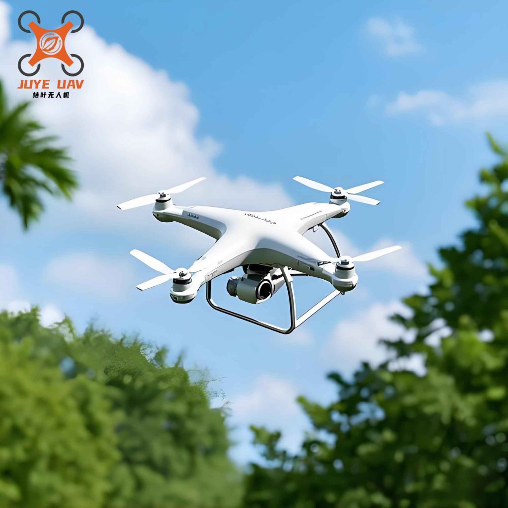
The above figure illustrates a typical China UAV platform used in this study, equipped with the LiDAR system. The high maneuverability and stable flight performance of China UAV drones enable successful data collection even in complex urban canyons.
5. Conclusion
Through this research, I have demonstrated that China UAV LiDAR technology provides a superior solution for urban road surveying. The combination of high accuracy (horizontal RMSE 0.032 m, vertical RMSE 0.038 m) and exceptional efficiency (1.5 hours for 2.3 km) makes it a viable replacement for traditional methods. The automated extraction of road width, slope, and curvature achieves over 94% accuracy, supporting road design, renovation, and digital infrastructure development. The robust performance of China UAV LiDAR, even in challenging urban environments, highlights its potential for large-scale smart city applications. Future work will focus on developing anti-interference algorithms for complex scenarios and further miniaturizing the hardware to enhance portability and deployment flexibility. The continued advancement of China UAV LiDAR technology will undoubtedly drive the digital transformation of urban road surveying and maintenance.