
The spectacle of a formation drone light show is a mesmerizing symphony of technology and art. Hundreds, sometimes thousands, of unmanned aerial vehicles (UAVs) move in perfect harmony, painting intricate, dynamic shapes against the night sky. While the visual poetry captures the audience’s imagination, the underlying technical choreography—ensuring every drone is in its exact designated position at the precise millisecond—is a formidable challenge in cooperative navigation and control. The core of this challenge lies in achieving and maintaining high-precision, real-time positioning for every member of the aerial fleet. Any significant drift in a drone’s perceived location can lead to collisions, distorted shapes, and a failed performance. Therefore, developing a robust and accurate navigation method is paramount for the reliable execution of complex formation drone light show sequences.
Traditional approaches for a single drone often rely heavily on Global Navigation Satellite Systems (GNSS), like GPS. However, in dense urban environments typical for formation drone light show venues, GPS signals can be reflected or blocked (multipath and shading), leading to degraded accuracy or complete loss. Relying solely on inertial navigation systems (INS) is not viable either, as their errors accumulate rapidly over time. For a coordinated formation drone light show, we must leverage the cooperative nature of the swarm itself. This article presents and simulates a distributed navigation method where one designated “leader” drone uses sensor fusion, while all “follower” drones augment their own navigation using relative measurements to this leader and to each other. This architecture enhances the overall system’s reliability and precision, crucial for a flawless formation drone light show.
System Architecture for Cooperative Navigation
We consider a fleet of n drones performing a formation drone light show. Each drone is equipped with a lightweight, commercial-grade Inertial Measurement Unit (IMU) providing accelerometer and gyroscope data, which is processed by an onboard INS to estimate attitude, velocity, and position. However, as mentioned, INS solutions drift. To counteract this, we establish a hierarchy and a shared data network.
- Leader Drone: One drone in the formation is designated as the leader. It is equipped with an additional GNSS receiver (e.g., GPS). This drone employs a classic INS/GNSS integrated navigation algorithm, using a Kalman filter to estimate and correct its own INS errors by fusing its inertial data with GNSS position and velocity updates.
- Follower Drones: The remaining n-1 drones are followers. They are not required to have a functional GNSS receiver for the system to work, making the fleet more resilient. Instead, each follower is equipped with a relative measurement system. For a formation drone light show, this is most feasibly a combination of:
- Inter-Drone Ranging: Using ultra-wideband (UWB) radios or similar precise timing technology, each drone can measure the distance (range) to its neighbors or to the leader with high accuracy (centimeter-level).
- Relative Bearing Estimation: Using simple onboard vision systems or directional antenna arrays, a drone can estimate the azimuth and elevation angles to nearby drones in its local field of view.
- Communication Network: All drones are connected via a high-speed, low-latency data link (like a TDMA-based radio network). The leader broadcasts its own corrected navigation state (position, velocity) periodically. Followers broadcast their own INS-derived states and may share relative measurements.
The core idea is that a follower drone can significantly improve its own position estimate by knowing where the leader should be relative to itself (based on the pre-planned formation geometry) and comparing that to where the leader appears to be based on direct relative measurements. This discrepancy primarily reveals the follower’s own INS error. The overall system architecture is conceptualized below.
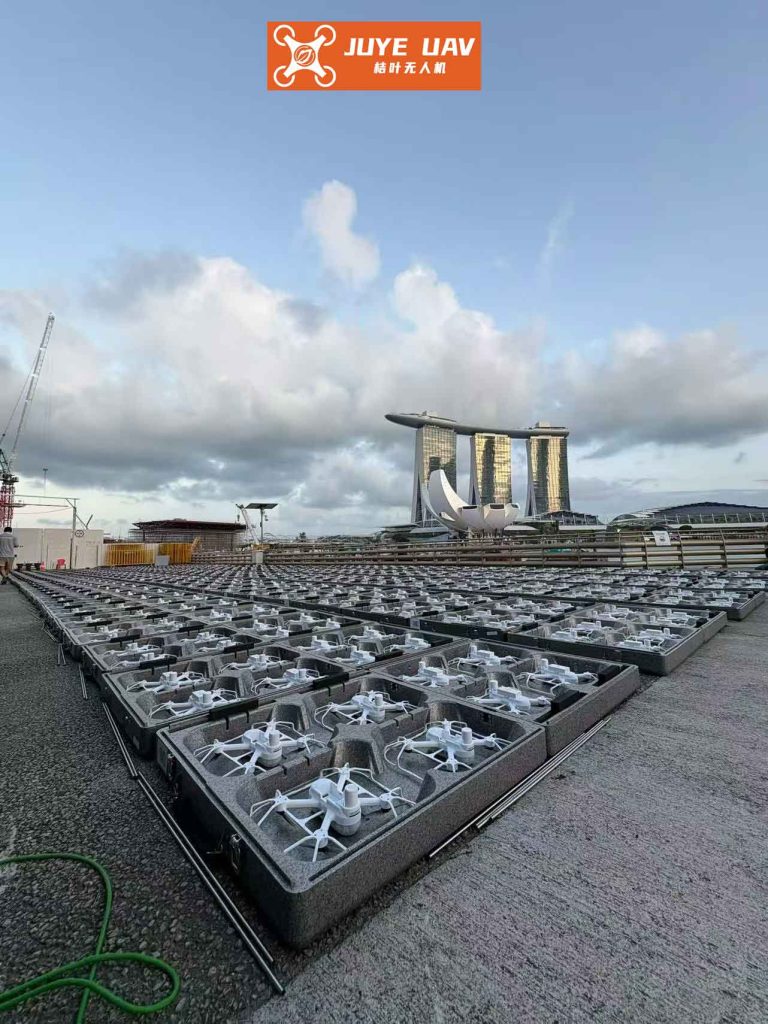
This image illustrates the concept of a tightly coordinated formation drone light show, where the precise relative positioning enabled by the proposed navigation framework allows for the creation of complex, luminous structures in three-dimensional space.
Mathematical Modeling of the Navigation System
1. INS Error State Model (Common to All Drones)
The INS on each drone, whether leader or follower, propagates its navigation solution, which contains errors. We define an error state vector for the INS of the i-th drone. For a local-level navigation frame (North-East-Down or East-North-Up), a typical 18-state error model is used:
$$
\mathbf{X}_i = [\phi_E, \phi_N, \phi_U, \delta v_E, \delta v_N, \delta v_U, \delta L, \delta \lambda, \delta h, \epsilon_x^b, \epsilon_y^b, \epsilon_z^b, \epsilon_x^r, \epsilon_y^r, \epsilon_z^r, \nabla_x, \nabla_y, \nabla_z]^T
$$
Where:
- $\phi_E, \phi_N, \phi_U$: Attitude (tilt) errors in East, North, and Up directions.
- $\delta v_E, \delta v_N, \delta v_U$: Velocity errors.
- $\delta L, \delta \lambda, \delta h$: Latitude, Longitude, and Height errors.
- $\epsilon^b, \epsilon^r$: Gyroscope bias and random walk errors (in body frame).
- $\nabla$: Accelerometer bias errors (in body frame).
The dynamics of these error states are well-known and are described by a linearized continuous-time state equation:
$$
\dot{\mathbf{X}}_i(t) = \mathbf{F}(t) \mathbf{X}_i(t) + \mathbf{G}(t) \mathbf{W}(t)
$$
Here, $\mathbf{F}(t)$ is the system dynamics matrix, which includes terms related to Earth’s rotation, transport rate, and specific force. $\mathbf{G}(t)$ is the noise input matrix, and $\mathbf{W}(t)$ is the process noise vector representing the driving noise of inertial sensors. This model forms the prediction step in a Kalman filter.
2. Leader Drone: INS/GNSS Fusion Model
The leader drone operates a standard centralized Kalman filter. The measurement (update) step uses the difference between its INS-derived position/velocity and the GNSS-provided position/velocity.
Measurement Vector:
$$
\mathbf{Z}_{leader} = \begin{bmatrix}
\mathbf{P}_{INS} – \mathbf{P}_{GNSS} \\
\mathbf{V}_{INS} – \mathbf{V}_{GNSS}
\end{bmatrix} = \begin{bmatrix}
\delta L \\
\delta \lambda \\
\delta h \\
\delta v_E \\
\delta v_N \\
\delta v_U
\end{bmatrix} + \mathbf{V}_{GNSS}
$$
This is essentially $\mathbf{Z}_{leader} = \mathbf{H}_{leader} \mathbf{X}_{leader} + \mathbf{V}_{GNSS}$, where $\mathbf{H}_{leader}$ is a matrix that simply selects the corresponding error states from $\mathbf{X}_{leader}$. The Kalman filter estimates $\mathbf{X}_{leader}$, which is then fed back to correct the leader’s INS, providing a high-accuracy reference trajectory for the entire formation drone light show.
3. Follower Drone: INS/Relative-Measurement Fusion Model
This is the novel and critical part for the swarm. Let’s consider Follower i. It has access to:
- Its own INS output: $(\hat{L}_i, \hat{\lambda}_i, \hat{h}_i)$ and $(\hat{v}_E^i, \hat{v}_N^i, \hat{v}_U^i)$.
- The leader’s corrected navigation state $(L_\ell, \lambda_\ell, h_\ell)$, received via data link.
- Direct range ($r_i$), azimuth ($\beta_i$), and elevation ($\alpha_i$) measurements to the leader, obtained from its onboard UWB and vision/bearing sensors.
The follower’s filter uses the discrepancy between the “calculated” and “measured” relative vector to the leader as its measurement.
Step 1: Calculate the relative vector from INS data.
First, convert both the follower’s INS position and the leader’s position from geodetic coordinates (Lat, Lon, Alt) to Earth-Centered Earth-Fixed (ECEF) coordinates, denoted as $(x, y, z)$.
For a spherical Earth model (simplified for clarity, WGS84 is used in practice):
$$
\begin{aligned}
x &= (R + h) \cos L \cos \lambda \\
y &= (R + h) \cos L \sin \lambda \\
z &= (R + h) \sin L
\end{aligned}
$$
where $R$ is Earth’s radius. The INS-calculated relative vector in ECEF frame is:
$$
\begin{bmatrix}
d_{ix}^{c} \\
d_{iy}^{c} \\
d_{iz}^{c}
\end{bmatrix}
=
\begin{bmatrix}
x_i^{INS} \\
y_i^{INS} \\
z_i^{INS}
\end{bmatrix}
–
\begin{bmatrix}
x_\ell \\
y_\ell \\
z_\ell
\end{bmatrix}
$$
Step 2: Express the sensor measurement in the same frame.
The raw measurements are range $r_i$, azimuth $\beta_i$ (angle in the local horizontal plane), and elevation $\alpha_i$. Assuming the follower can estimate its own attitude (from its INS, corrected by the filter), it can transform this local spherical measurement into the ECEF frame vector $\mathbf{d}_i^{m}$.
$$
\mathbf{d}_i^{m} = r_i \cdot \mathbf{u}_i(\alpha_i, \beta_i) + \mathbf{v}_i
$$
where $\mathbf{u}_i$ is the unit vector derived from the angles, and $\mathbf{v}_i$ is the measurement noise.
Step 3: Form the measurement innovation.
The measurement for the Kalman filter is the difference between the calculated and measured relative vectors:
$$
\mathbf{Z}_i = \mathbf{d}_i^{c} – \mathbf{d}_i^{m}
$$
Step 4: Relate innovation to the follower’s error state.
The key insight is that $\mathbf{d}_i^{c}$ is computed using the follower’s erroneous INS position $(x_i^{INS} = x_i^{true} + \delta x_i, …)$. The leader’s position $(x_\ell, y_\ell, z_\ell)$ is assumed accurate (its errors are negligible compared to the follower’s uncorrected INS error). Therefore:
$$
\mathbf{d}_i^{c} = (\mathbf{p}_i^{true} + \delta \mathbf{p}_i) – \mathbf{p}_\ell = \mathbf{d}_i^{true} + \delta \mathbf{p}_i
$$
where $\delta \mathbf{p}_i = [\delta x_i, \delta y_i, \delta z_i]^T$ is the follower’s position error in ECEF. The measurement model becomes:
$$
\mathbf{Z}_i = \mathbf{d}_i^{true} + \delta \mathbf{p}_i – (\mathbf{d}_i^{true} + \mathbf{v}_i) = \delta \mathbf{p}_i – \mathbf{v}_i
$$
Finally, we need $\delta \mathbf{p}_i$ in terms of the filter’s error state $\delta L_i, \delta \lambda_i, \delta h_i$. This requires the Jacobian of the coordinate transformation:
$$
\delta \mathbf{p}_i =
\begin{bmatrix}
\delta x_i \\
\delta y_i \\
\delta z_i
\end{bmatrix}
= \mathbf{J}_i \cdot
\begin{bmatrix}
\delta L_i \\
\delta \lambda_i \\
\delta h_i
\end{bmatrix}, \quad \text{where } \mathbf{J}_i = \frac{\partial (x,y,z)}{\partial (L, \lambda, h)}
$$
Thus, the final measurement model for a follower drone is:
$$
\mathbf{Z}_i = \mathbf{H}_i \mathbf{X}_i + \mathbf{V}_i, \quad \text{with } \mathbf{H}_i = [\mathbf{0}_{3\times6} \ \ \mathbf{J}_i \ \ \mathbf{0}_{3\times9}]
$$
where $\mathbf{V}_i$ is the noise vector encapsulating errors from ranging and angle measurements. Its covariance matrix $\mathbf{R}_i$ can be derived based on the accuracy specs of the UWB and vision sensors.
This elegant formulation shows that by measuring the relative vector to a known reference (the leader), a follower drone can directly observe a linear combination of its own position errors, enabling the Kalman filter to estimate and correct its entire INS error state. This process, running in real-time on every follower, is what enables the precise station-keeping required for a complex formation drone light show.
Simulation Design and Results Analysis
To validate the proposed cooperative navigation framework for a formation drone light show, a numerical simulation was developed. The scenario involves one leader drone and two follower drones performing a slow, coordinated maneuver over 300 seconds, simulating a segment of a light show performance.
Simulation Parameters:
| Component | Parameter | Value / Specification |
|---|---|---|
| INS (All Drones) | Gyro Bias (1σ) | 10 °/hr |
| Gyro White Noise | 0.5 °/√hr | |
| Accelerometer Bias (1σ) | 1 mg | |
| Leader GNSS | Position Accuracy (1σ) | Horizontal: 1.5 m, Vertical: 2.5 m |
| Follower Relative Sensors | UWB Range Accuracy (1σ) | 0.1 m |
| Bearing Accuracy (1σ) | 0.5° (both azimuth & elevation) | |
| Filter | Update Rate | 1 Hz (for both leader GNSS & follower relative meas.) |
Simulation Results:
The following table summarizes the steady-state navigation accuracy (Root Mean Square Error – RMSE) achieved by each drone over the simulation period after the Kalman filters have converged.
| Drone Role | Position RMSE (Horizontal) | Position RMSE (Vertical) | Velocity RMSE (3D) |
|---|---|---|---|
| Leader (INS/GNSS) | 1.8 m | 2.1 m | 0.05 m/s |
| Follower 1 (INS/Relative) | 2.5 m | 3.8 m | 0.12 m/s |
| Follower 2 (INS/Relative) | 2.7 m | 4.0 m | 0.13 m/s |
The results clearly demonstrate the effectiveness of the method. The leader drone, benefiting from direct GNSS updates, achieves the best accuracy. Crucially, the follower drones, which do not use GNSS at all in this simulation, maintain positioning accuracy within 2-4 meters and velocity accuracy better than 0.15 m/s. This level of performance is more than sufficient for a formation drone light show, where inter-drone spacing is typically 1-3 meters. The key metric for the show is relative positioning, which is even more accurate because correlated errors (like the leader’s minor position error) partially cancel out when calculating the relative geometry between followers.
The convergence behavior is also critical. In the simulation, the followers’ Kalman filters converged to steady-state performance within 60-80 seconds from initialization, even starting from large initial attitude and position uncertainties. This quick convergence is vital for a real-world formation drone light show where drones take off and must acquire precise formation holding rapidly.
Discussion and Implications for Formation Drone Light Shows
The proposed architecture offers several compelling advantages specifically tailored for large-scale formation drone light show productions:
- Robustness to GNSS Degradation: Only one drone requires a high-quality GNSS signal. If the leader’s GNSS is temporarily jammed or degraded, the formation can continue operating based on the leader’s high-grade INS and the web of relative measurements among all drones, preventing a catastrophic failure of the show.
- Scalability and Cost-Effectiveness: Equipping every drone in a 1000-drone show with a survey-grade GNSS/INS system is prohibitively expensive. This method allows the bulk of the fleet to use low-cost IMUs and relative sensors, with only a few “anchor” drones needing advanced navigation suites, dramatically reducing system cost.
- Enhanced Relative Accuracy: The direct use of inter-drone ranging (<1m accuracy) provides a tighter bound on the relative geometry than absolute GNSS positioning ever could, especially in challenging signal environments. This is the primary requirement for a visually crisp formation drone light show.
- Redundancy: The leader role can be dynamically reassigned if necessary. If the primary leader fails, another drone with a GNSS receiver (or the best INS) can assume the role, and the network can reconfigure.
Potential extensions to this core algorithm for an even more spectacular formation drone light show include incorporating measurements between followers (not just follower-to-leader), creating a resilient mesh network of navigation data. Furthermore, the planned show trajectory and choreography itself can be used as a “soft constraint” within the filter, further bounding drift during periods with fewer good relative measurements.
Conclusion
The pursuit of ever more ambitious and precise aerial displays drives innovation in swarm navigation. The cooperative navigation framework presented here, which synergistically combines a GNSS-augmented leader with relatively-measuring followers through decentralized Kalman filtering, provides a robust, accurate, and practical solution to the core challenge of multi-drone positioning. By transforming the swarm from a collection of independently navigating vehicles into a mutually-aware sensing network, this method ensures that each drone knows its place in the sky with remarkable precision. This technological foundation is what allows hundreds of luminous points to move as one, translating digital artistry into breathtaking physical reality and pushing the boundaries of what is possible in a modern formation drone light show. As the algorithms and sensors continue to improve, we can expect these aerial ballets to become even more complex, dynamic, and awe-inspiring.