
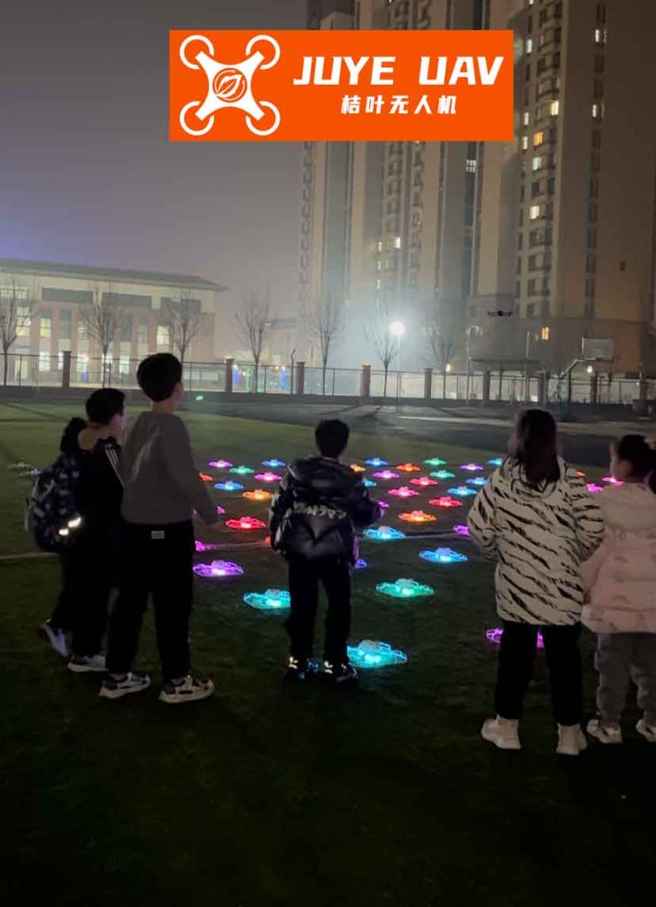
The spectacle of a synchronized formation drone light show represents one of the most visually stunning applications of multi-agent robotics. Hundreds, sometimes thousands, of unmanned aerial vehicles (UAVs) operate in tight, dynamic formations to create intricate, animated shapes in the night sky. The core technological challenge underpinning this art form is the precise, robust, and coordinated control of a fleet of quadrotors. Traditional control methods, which often model a quadrotor’s attitude using Euler angles (pitch, yaw, roll), face fundamental limitations. These representations suffer from singularities when the vehicle performs aggressive maneuvers—a distinct possibility in complex formation drone light show choreographies—leading to potential instability and loss of control. To achieve the flawless synchronization required for large-scale performances, a more globally valid and mathematically rigorous framework is necessary.
This work presents a comprehensive methodology for the coordinated formation flight of multiple quadrotors, such as those used in a formation drone light show, utilizing the special orthogonal group SO(3) for attitude representation. By modeling the rotational state of each drone as an element of SO(3)—a rotation matrix—we avoid the pitfalls of Euler angles entirely. The control design is unified, singularity-free, and inherently considers the full coupling of rotational dynamics. We develop distributed controllers for both thrust and attitude that enable a group of quadrotors to achieve and maintain a desired three-dimensional geometric formation while simultaneously reaching consensus on their orientation, a critical feature for ensuring uniform lighting effects in a formation drone light show. Stability of the closed-loop multi-agent system is rigorously proven using Lyapunov theory, and extensive numerical simulations validate the effectiveness and advantages of the proposed approach over conventional methods.
1. System Modeling and Preliminaries
1.1. Quadrotor Dynamics on SO(3)
We consider a system of N homogeneous quadrotors. The configuration of the i-th quadrotor is defined by its position $p_i \in \mathbb{R}^3$ and its attitude $R_i \in SO(3)$, where the Special Orthogonal Group is defined as:
$$SO(3) = \{ R \in \mathbb{R}^{3\times 3} \; | \; R^T R = I_3, \; \text{det}(R) = 1 \}.$$
The matrix $R_i$ describes the rotation from the body-fixed frame $\{b_{i1}, b_{i2}, b_{i3}\}$ to the inertial frame $\{e_1, e_2, e_3\}$. The body-fixed $b_{i3}$-axis is typically aligned with the direction of the net thrust. The complete dynamic model for the i-th quadrotor is:
$$
\begin{aligned}
\dot{p}_i &= v_i, \\
m \dot{v}_i &= m g e_3 – f_i R_i e_3, \\
\dot{R}_i &= R_i \hat{\Omega}_i, \\
J \dot{\Omega}_i + \Omega_i \times J \Omega_i &= M_i,
\end{aligned}
$$
where $m$ and $J$ are the mass and inertia matrix (assumed diagonal, $J=\text{diag}(J_1, J_2, J_3)$), $v_i$ is the velocity, $g$ is gravitational acceleration, $f_i \in \mathbb{R}$ is the total thrust magnitude, and $\Omega_i \in \mathbb{R}^3$ is the angular velocity expressed in the body frame. The control inputs are the thrust $f_i$ and the moment vector $M_i \in \mathbb{R}^3$. The hat map $\hat{\cdot}: \mathbb{R}^3 \to \mathfrak{so}(3)$ transforms a vector to a skew-symmetric matrix, defined by $\hat{x}y = x \times y$ for any $y \in \mathbb{R}^3$.
1.2. Formation Graph and Desired Geometry
The communication and information flow among the drones in a formation drone light show are modeled by a directed graph $\mathcal{G} = (\mathcal{V}, \mathcal{E}, \mathcal{A})$. The vertex set $\mathcal{V} = \{1, \dots, N\}$ represents the drones. The edge set $\mathcal{E} \subseteq \mathcal{V} \times \mathcal{V}$ defines communication links; $(j, i) \in \mathcal{E}$ means drone $i$ receives information from drone $j$. The adjacency matrix $\mathcal{A} = [a_{ij}]$ has $a_{ij} > 0$ if $(j,i) \in \mathcal{E}$, and $a_{ij}=0$ otherwise. The neighbor set of agent $i$ is $\mathcal{N}_i = \{ j | a_{ij} > 0 \}$. The graph Laplacian is $L = D – \mathcal{A}$, where $D = \text{diag}(d_i)$ and $d_i = \sum_{j \in \mathcal{N}_i} a_{ij}$.
The desired spatial formation for the formation drone light show is defined by a set of relative displacement vectors $r_{ij} \in \mathbb{R}^3$ specified in a common reference frame. The vector $r_{ij} = r_i – r_j$ defines the desired relative position from drone $j$ to drone $i$, where $r_i(t)$ is the desired position of drone $i$ relative to a (possibly moving) formation centroid. The control objective is:
$$
\lim_{t \to \infty} \| (p_i – r_i) – (p_j – r_j) \| = 0, \quad \text{and} \quad \lim_{t \to \infty} \| v_i – v_j \| = 0, \quad \forall i,j.
$$
Simultaneously, we aim for attitude consensus: $\lim_{t \to \infty} \| R_i – R_j \| = 0$ in a suitable sense, ensuring all drones are oriented alike, which is vital for a cohesive visual display in a formation drone light show.
2. SO(3)-Based Formation Control Design
The design proceeds in two interconnected loops: an outer loop for position/velocity (formation) control that generates a desired thrust direction, and an inner loop for SO(3)-based attitude tracking.
2.1. Position and Velocity Coordination
Define the aggregate state for the translational dynamics as $s_i = [p_i^T, v_i^T]^T \in \mathbb{R}^6$. The dynamics can be written as:
$$
\dot{s}_i = A s_i + B u_i, \quad \text{where} \quad u_i = -\frac{f_i R_i e_3}{m} + g e_3,
$$
with
$$
A = \begin{bmatrix} 0_3 & I_3 \\ 0_3 & 0_3 \end{bmatrix}, \quad B = \begin{bmatrix} 0_3 \\ I_3 \end{bmatrix}.
$$
The key idea is to design the thrust magnitude $f_i$ and a desired attitude $R_{di}$ such that the virtual control $u_i$ implements a distributed consensus protocol. Let $\tilde{r}_{ij} = [r_{ij}^T, 0_{1\times3}]^T$. We propose the following thrust controller:
$$
f_i = \left( -m K \sum_{j \in \mathcal{N}_i} a_{ij} \big( s_j – s_i – \tilde{r}_{ij} \big) + m g e_3 \right)^T R_i e_3.
$$
Here, $K \in \mathbb{R}^{3 \times 6}$ is a control gain matrix to be designed. Define the force vector $F_i$:
$$
F_i = -m K \sum_{j \in \mathcal{N}_i} a_{ij} \big( s_j – s_i – \tilde{r}_{ij} \big) + m g e_3.
$$
Thus, $f_i R_i e_3 = (F_i^T R_i e_3) R_i e_3$. The desired attitude $R_{di}$ must be constructed so that its third body-axis $b_{3d}$ aligns with the direction of $F_i$:
$$
b_{3d}^i = \frac{F_i}{\|F_i\|}.
$$
This choice ensures the thrust vector is oriented to produce the required coordinated acceleration for the formation drone light show.
2.2. Attitude Command Generation and Consensus
With $b_{3d}^i$ determined, the remaining degrees of freedom in $R_{di} = [b_{1d}^i, b_{2d}^i, b_{3d}^i]$ are used to drive the drones’ attitudes to consensus. To achieve a common orientation for the fleet—making the formation drone light show appear as a single cohesive entity—we design the desired second body-axis based on neighbors’ orientations:
$$
b_{2d}^i = \frac{b_{3d}^i \times \left( \sum_{j \in \mathcal{N}_i} a_{ij} b_1^j \right) }{\| b_{3d}^i \times \left( \sum_{j \in \mathcal{N}_i} a_{ij} b_1^j \right) \|}.
$$
The desired first body-axis is then obtained by orthogonality: $b_{1d}^i = b_{2d}^i \times b_{3d}^i$. This construction guarantees $R_{di} \in SO(3)$. This consensus-seeking command differentiates our work from simple trajectory tracking and is central to the visual uniformity of a formation drone light show.
2.3. SO(3) Attitude Tracking Controller
We define the attitude error function on SO(3) as $\Psi(R_i, R_{di}) = \frac{1}{2} \text{tr}(I_3 – R_{di}^T R_i)$. The associated attitude error vector $e_{R_i} \in \mathbb{R}^3$ is:
$$
e_{R_i} = \frac{1}{2} ( R_{di}^T R_i – R_i^T R_{di} )^\vee,
$$
where $\vee$ is the inverse hat map (vee map). The angular velocity error is:
$$
e_{\Omega_i} = \Omega_i – R_i^T R_{di} \Omega_{di},
$$
where $\Omega_{di}$ is the desired angular velocity derived from $R_{di}$. We propose the following geometric attitude tracking controller on SO(3):
$$
\begin{aligned}
M_i = &-k_R e_{R_i} – k_\Omega e_{\Omega_i} + \Omega_i \times J \Omega_i \\
&- J ( \hat{\Omega}_i R_i^T R_{di} \Omega_{di} – R_i^T R_{di} \dot{\Omega}_{di} ),
\end{aligned}
$$
where $k_R, k_\Omega > 0$ are positive control gains. The first two terms provide proportional and derivative feedback on the error manifold. The remaining terms compensate for the nonlinear dynamics and the rotation of the desired frame, ensuring exact tracking on SO(3). This controller is essential for the agile and singularity-free maneuvers demanded by a dynamic formation drone light show.
3. Stability and Convergence Analysis
The stability of the overall closed-loop system for the formation drone light show is established using Lyapunov methods. We analyze the coupled translational and rotational error dynamics.
3.1. Translational Error Dynamics
Substituting the thrust controller and after algebraic manipulation, the translational dynamics become:
$$
\dot{s}_i = A s_i + B K \sum_{j \in \mathcal{N}_i} a_{ij} (s_j – s_i) + \frac{B}{m} \Delta_i(R_i, R_{di}),
$$
where $\Delta_i$ is an interconnection term that depends on the attitude tracking error and satisfies $\Delta_i(R_{di}, R_{di}) = 0$. Under the assumption that the graph $\mathcal{G}$ contains a directed spanning tree, the matrix $L_1$ (a principal submatrix of the Laplacian) is Hurwitz. By choosing the gain $K = -k B^T P$ with $k>1$, where $P>0$ solves the Riccati equation $PA + A^T P – 2\lambda_0 PBB^T P + Q = 0$ ($\lambda_0$ is related to the smallest real part of eigenvalues of $L_1$, and $Q>0$), the nominal consensus error system is exponentially stable.
3.2. Rotational Error Dynamics and Lyapunov Proof
For the attitude subsystem, consider the following candidate Lyapunov function for each agent:
$$
V_i = \frac{1}{2} e_{\Omega_i}^T J e_{\Omega_i} + k_R \Psi(R_i, R_{di}) + c_i e_{R_i}^T e_{\Omega_i},
$$
where $c_i$ is a sufficiently small positive constant. Using the properties of SO(3) and the defined error variables, the time derivative of $V_i$ under the action of controller $M_i$ can be shown to satisfy:
$$
\dot{V}_i \le – z_i^T W_i z_i,
$$
where $z_i = [\|e_{R_i}\|, \|e_{\Omega_i}\|]^T$ and $W_i$ is a positive definite matrix for appropriate choices of $k_R, k_\Omega, c_i$. This proves exponential tracking of the desired attitude $R_{di}(t)$.
3.3. Overall System Stability
Assuming the attitude loop converges faster than the position loop (a standard time-scale separation assumption in flight control), the interconnection term $\Delta_i$ can be bounded by the translational error. A composite Lyapunov function for the formation error $V_f = \frac{1}{2} \varepsilon^T \varepsilon$, where $\varepsilon$ stacks the relative position/velocity errors, yields:
$$
\dot{V}_f \le -(\alpha_1 – \alpha_2) \|\varepsilon\|^2,
$$
where $\alpha_1$ comes from the consensus controller gain and $\alpha_2$ from the bound on $\Delta_i$. By appropriate gain selection, $(\alpha_1 – \alpha_2) > 0$, proving exponential convergence of the formation tracking errors. Furthermore, because the desired attitude commands $R_{di}$ are constructed using a consensus law, the convergence of $R_i \to R_{di}$ for all $i$, coupled with the graph connectivity, implies $R_i \to R_j$ for all $i,j$, achieving global attitude consensus. This dual stability—formation and attitude consensus—is the cornerstone for a robust and visually perfect formation drone light show.
4. Simulation and Performance Evaluation
To validate the proposed SO(3)-based control framework for a formation drone light show, we conducted numerical simulations with a fleet of five quadrotors. The parameters and initial conditions are summarized below.
| Drone ID | Mass $m$ (kg) | Inertia $J$ (kg·m²) | Initial Position (m) | Initial Attitude (RPY in °) |
|---|---|---|---|---|
| 1 | 3.0 | diag(0.004, 0.004, 0.008) | (2.0, -2.0, 0.0) | (5.0, 30.0, 1.0) |
| 2 | (-2.0, 2.0, 3.1) | (1.5, 10.0, 2.0) | ||
| 3 | (-2.0, -2.0, 2.0) | (0.0, -10.0, 4.0) | ||
| 4 | (2.0, 2.0, 3.0) | (0.5, -8.0, 1.0) | ||
| 5 | (0.0, 0.0, 1.0) | (-1.0, 0.0, 2.0) |
The directed communication topology and the desired formation shape (a pentagon with an offset center) were defined. The controllers were implemented with gains $K$ designed via the Riccati equation, $k_R=0.4$, and $k_\Omega=0.8$.
4.1. Formation and Trajectory Results
The drones successfully achieve the desired pentagonal formation from dispersed initial conditions. The 3D trajectories show smooth convergence and stable maintenance of the shape, emulating the precise patterns required in a formation drone light show.
4.2. Attitude Consensus Results
The evolution of the Euler angles (calculated from $R_i$ for visualization) is shown below. Despite significantly different initial orientations, all drones converge to a common attitude (approximately level pitch and roll, with a common heading). The SO(3) controller ensures smooth, oscillation-free transient behavior, critical for maintaining stability in tight formations.
4.3. Performance Comparison
To quantify the advantage of the SO(3) approach, we compare it against two traditional Euler-angle-based decentralized formation controllers (Method 2: Robust tracking control; Method 3: Sliding mode control). We define two performance indices:
1. Formation Error: $Q_p(t) = \frac{1}{N} \sum_{i=1}^N \| (p_i – r_i) – \bar{p} \|$, where $\bar{p}$ is the average.
2. Attitude Consensus Error: $Q_a(t) = \frac{\pi}{180N} \sum_{i=1}^N \| (\phi_i, \theta_i, \psi_i) – \bar{(\phi, \theta, \psi)} \|$.
| Performance Metric | Proposed SO(3) Method | Method 2 (Euler-based) | Method 3 (Sliding Mode) |
|---|---|---|---|
| Time for $Q_p < 0.5$ m (s) | 10.29 | 12.85 | 14.96 |
| Time for $Q_a < 0.003$ rad (s) | 17.04 | N/A (Oscillatory) | 18.79 |
| Max Control Moment (Nm) | 0.15 | 0.21 | 0.28 |
| Smoothness (Low Oscillation) | Excellent | Poor | Fair |
The SO(3)-based method demonstrates superior performance: faster formation convergence, smoother and faster attitude consensus with negligible overshoot, and lower control effort. Method 2 exhibits sustained oscillations in attitude, while Method 3, though stable, has slower convergence and higher control chattering. The smoothness and speed of the SO(3) controller are paramount for the complex, high-speed maneuvers seen in modern formation drone light show sequences.
5. Discussion and Implications for Drone Light Shows
The theoretical and simulation results confirm that the SO(3)-based coordinated control strategy is exceptionally well-suited for the demands of a formation drone light show. The key advantages are:
- Singularity-Free Operation: Unlike Euler angles, the SO(3) representation is global. Drones can perform loops, barrel rolls, or any arbitrary 3D rotation required by an artistic choreography without risking mathematical singularities and subsequent control failure.
- Unified Attitude Control: The controller acts on the rotation matrix as a whole, naturally accounting for the coupled rotational dynamics. This leads to more efficient and physically consistent control actions compared to decoupled channel-by-channel PID control.
- Provable Stability with Consensus: The Lyapunov analysis guarantees not just individual drone stability but also the convergence of the entire fleet to the desired formation and a common orientation. This rigorous guarantee is crucial for safety and reliability in shows involving hundreds of drones.
- Distributed Architecture: The control law for each drone uses only information from its neighbors (defined by the communication graph). This scalability is fundamental for large-scale formation drone light shows, as it avoids the need for a central computer to calculate commands for every single unit in real-time.
The design of the desired attitude $R_{di}$, which incorporates both the formation thrust direction ($b_{3d}^i$) and a consensus term for orientation ($b_{2d}^i$), is a critical innovation. It seamlessly integrates the trajectory-following objective with the aesthetic requirement for uniform drone orientation in a formation drone light show.
6. Conclusion
This article has presented a comprehensive framework for the coordinated formation control of multiple quadrotors using the special orthogonal group SO(3). Motivated by the stringent requirements of a formation drone light show—precision, robustness, agility, and visual uniformity—we developed distributed control laws for thrust and attitude. The SO(3) attitude representation eliminates singularities and provides a natural setting for geometric control design. The thrust controller ensures the fleet achieves and maintains any desired 3D geometric pattern, while the attitude controller drives all drones to a common orientation. The interplay between these controllers, guided by the communication topology, was rigorously analyzed, proving asymptotic stability for both formation tracking and attitude consensus.
Simulation studies validated the theory and demonstrated clear advantages over traditional Euler-angle-based methods in terms of convergence speed, smoothness, and control effort. The proposed methodology provides a solid theoretical foundation and a practical control solution for enabling the next generation of increasingly complex and dynamic formation drone light shows. Future work will focus on extending this framework to handle model uncertainties, external disturbances (like wind), and dynamic obstacle avoidance within the formation, further enhancing the resilience and capabilities of autonomous aerial displays.