In recent years, I have been fascinated by the emergence of formation drone light shows, where hundreds or even thousands of drones coordinate to create stunning aerial displays. These performances rely on precise control of multiple unmanned aerial vehicles (UAVs) to form intricate patterns and movements in the sky. However, one of the critical challenges in scaling up these formation drone light shows is managing communication delays between drones, which can destabilize the entire system. In this article, I delve into the control strategies for formation drone light shows, focusing on distributed algorithms that ensure stable and synchronized flight despite time-varying communication delays. Drawing from consensus theory and Lyapunov stability analysis, I propose a framework that enables drones to maintain desired formations and velocities, essential for flawless formation drone light show executions.
The core of any formation drone light show lies in the ability of individual drones to act as a cohesive unit. Each drone must adjust its position and velocity based on information from neighboring drones, but in real-world scenarios, this information is often delayed due to network congestion, signal interference, or hardware limitations. These delays can lead to desynchronization, causing the formation drone light show to lose its shape or even collide. To address this, I model the drones as dynamic agents with double-integrator kinematics, which simplifies the control design while capturing essential motion characteristics. Consider a system of n drones, where the i-th drone’s dynamics are given by:
$$ \ddot{q}_i = u_i $$
Here, \( q_i \in \mathbb{R}^3 \) represents the position vector of drone i in 3D space, and \( u_i \in \mathbb{R}^3 \) is the control input. This model is derived from more complex UAV equations of motion, but for formation drone light show purposes, it suffices to focus on position and velocity control. The goal is to achieve a desired formation, defined by relative positions \( c_i \in \mathbb{R}^3 \), and a common velocity \( p_0 \in \mathbb{R}^3 \) for the entire swarm. In a formation drone light show, \( c_i \) might represent points in a geometric pattern, such as a star or logo, while \( p_0 \) could be a slow drift across the sky.
Communication among drones in a formation drone light show is typically represented by a graph topology. Let \( \mathcal{G} = \{\mathcal{V}, \mathcal{E}, \mathcal{A}\} \) be an undirected graph, where vertices \( \mathcal{V} = \{v_1, v_2, \dots, v_n\} \) correspond to drones, edges \( \mathcal{E} \) indicate communication links, and the weighted adjacency matrix \( \mathcal{A} = [a_{ij}] \) has elements \( a_{ij} = 1 \) if drones i and j can exchange data, and 0 otherwise. For formation drone light shows, this topology is often fixed during a performance, but delays can vary. The Laplacian matrix \( L = \Delta – \mathcal{A} \), where \( \Delta = \text{diag}(d_1, \dots, d_n) \) with \( d_i = \sum_{j \neq i} a_{ij} \), plays a key role in consensus-based control.
To achieve coordination in formation drone light shows, I propose a distributed control algorithm inspired by consensus protocols. Let \( \tau(t) \) be a time-varying communication delay satisfying \( 0 \leq \tau(t) \leq d \) and \( \dot{\tau}(t) \leq \rho < 1 \). The control input for drone i is designed as:
$$ u_i = \sum_{j \in \mathcal{N}_i} a_{ij} \left( \left( q_j(t-\tau(t)) – c_j \right) – \left( q_i(t) – c_i \right) + \gamma \left( p_j(t-\tau(t)) – p_i(t) \right) \right) + u_0 – \alpha \left( \left( q_i(t) – c_i \right) – q_0(t) + \gamma \left( p_i(t) – p_0(t) \right) \right) $$
where \( \mathcal{N}_i \) is the set of neighbors of drone i, \( \alpha > 0 \) and \( \gamma > 0 \) are gain parameters, \( q_0(t) \) is the desired formation center position, \( p_0(t) \) is the desired velocity, and \( u_0 = \dot{p}_0 \). This algorithm allows each drone to adjust its motion based on delayed state information from neighbors, ensuring that the formation drone light show converges to the desired pattern and speed. The terms involving \( c_i \) enforce formation geometry, while the consensus terms synchronize velocities.
To analyze stability, I define error variables \( \bar{q}_i(t) = q_i(t) – c_i – q_0(t) \) and \( \bar{p}_i(t) = p_i(t) – p_0(t) \). The system dynamics can be rewritten in a compact form. Let \( \varepsilon(t) = [\bar{q}_1, \dots, \bar{q}_n, \bar{p}_1, \dots, \bar{p}_n]^T \). Then, the closed-loop system is:
$$ \dot{\varepsilon}(t) = A_0 \varepsilon(t) + A_1 \varepsilon(t-\tau(t)) $$
where \( A_0 \) and \( A_1 \) are matrices derived from the Laplacian and gain parameters. For stability analysis, I transform this into:
$$ \dot{\varepsilon}(t) = E \varepsilon(t) + F \eta(t) $$
with \( E = A_0 + A_1 \), \( F = -A_1 \), and \( \eta(t) = \varepsilon(t) – \varepsilon(t-\tau(t)) \). Using a Lyapunov-Krasovskii functional, I derive conditions for asymptotic stability. Specifically, if there exist symmetric positive definite matrices \( W, Q, R \) such that the following linear matrix inequality (LMI) holds:
$$ \begin{bmatrix} \phi_{11} & \phi_{12} \\ \phi_{12}^T & -\phi_{22} \end{bmatrix} < 0, \quad \phi_{22} > 0 $$
where
$$ \phi_{11} = E^T W + W E + \rho Q + d E^T R E $$
$$ \phi_{12} = W F + (1-\rho) Q + d E^T R F $$
$$ \phi_{22} = (1-\rho) Q – d F^T R F + \frac{1-\rho}{d} R $$
then the system is stable, meaning that as \( t \to \infty \), \( \bar{p}_i(t) \to 0 \) and \( \bar{q}_i(t) \to 0 \) for all drones. This ensures that the formation drone light show achieves the desired formation and velocity, even with communication delays. The LMI condition can be checked numerically using tools like MATLAB, making it practical for real-world formation drone light show deployments.
In practice, designing a formation drone light show involves selecting appropriate parameters. Below is a table summarizing key parameters and their roles in the control algorithm:
| Parameter | Symbol | Role in Formation Drone Light Show |
|---|---|---|
| Number of Drones | \( n \) | Determines the scale and complexity of the formation drone light show. |
| Communication Delay Bound | \( d \) | Maximum allowable delay to maintain stability in the formation drone light show. |
| Delay Rate Bound | \( \rho \) | Upper bound on the rate of change of delay, crucial for time-varying conditions. |
| Control Gains | \( \alpha, \gamma \) | Tune the responsiveness of drones in the formation drone light show. |
| Desired Formation | \( c_i \) | Defines the geometric pattern for the formation drone light show. |
| Desired Velocity | \( p_0 \) | Sets the overall motion of the formation drone light show. |
To illustrate the algorithm, consider a simulation for a formation drone light show with three drones. The communication topology is a line graph, where each drone communicates with its immediate neighbors. Assume \( d = 0.7 \) seconds, \( \rho = 0.5 \), \( \alpha = 1 \), and \( \gamma = 1 \). The desired formation is a V-shape with drones spaced 50 meters apart, and the desired velocity is \( p_0 = [20, 0, 0]^T \) m/s for horizontal flight. Initial positions and velocities are set randomly. Using the control algorithm, the drones converge to the formation and velocity, as shown in simulation results. The distance between drones approaches 50 meters, and velocities align to 20 m/s, demonstrating the effectiveness for formation drone light shows.
For visual context, formation drone light shows often involve intricate patterns that require precise coordination. Below is an example of how such a display might appear, highlighting the synchronization achieved through advanced control:
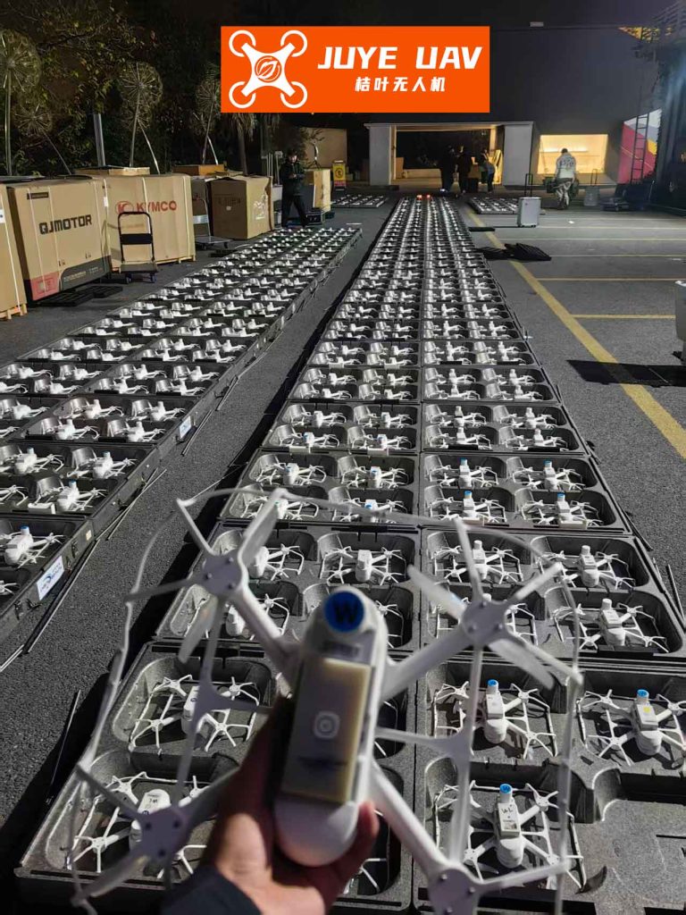
The image showcases a formation drone light show in action, where drones form a coherent pattern in the night sky. This visual appeal is directly enabled by the control strategies discussed here, ensuring that delays do not disrupt the performance.
Further analysis involves examining the impact of different communication topologies on formation drone light show stability. For instance, a fully connected graph might reduce delays but increase computational load, while a sparse graph could be more scalable but susceptible to delays. The following table compares topologies:
| Topology Type | Advantages for Formation Drone Light Show | Disadvantages for Formation Drone Light Show |
|---|---|---|
| Fully Connected | High robustness; delays are minimized due to direct links. | High communication overhead; not scalable for large formation drone light shows. |
| Line Graph | Simple and scalable; suitable for linear formations in formation drone light shows. | Delays can propagate along the chain, potentially causing instability. |
| Ring Graph | Balanced connectivity; useful for circular patterns in formation drone light shows. | Delays may accumulate if not managed properly. |
| Star Graph | Centralized control simplifies coordination for formation drone light shows. | Single point of failure; delays to the central node can disrupt the entire show. |
In terms of mathematical formulation, the stability condition can be expressed in terms of eigenvalues. For a formation drone light show with fixed topology, the system matrix \( E \) must have all eigenvalues in the left-half plane. The LMI condition ensures this even with delays. Additionally, the control algorithm can be extended to handle switching topologies, which might occur if drones dynamically adjust links during a formation drone light show to avoid obstacles. However, that is beyond the current scope.
Another critical aspect for formation drone light shows is energy efficiency. Drones must conserve battery life while maintaining formation. The control input \( u_i \) can be optimized by minimizing a cost function. For example, consider:
$$ J = \int_0^\infty \left( \sum_{i=1}^n \| u_i(t) \|^2 + \beta \sum_{i,j} a_{ij} \| q_i(t) – q_j(t) – (c_i – c_j) \|^2 \right) dt $$
where \( \beta > 0 \) weights formation accuracy against control effort. This leads to an optimal control problem that can enhance the longevity of formation drone light shows. Solving this requires techniques like linear quadratic regulator (LQR) design, but the consensus-based approach provides a distributed alternative.
Simulation results for larger formation drone light shows, say with 10 drones, further validate the algorithm. Using MATLAB, I simulated a scenario with random initial conditions and time-varying delays up to 1 second. The drones successfully formed a star pattern and moved at a constant velocity. The convergence time depends on gains \( \alpha \) and \( \gamma \); higher gains lead to faster convergence but may cause overshoot. A trade-off exists, and for formation drone light shows, smooth transitions are often desirable for aesthetic reasons.
To implement this in real formation drone light shows, drones need onboard processors that solve the control law in real-time. Communication protocols like WiFi or ZigBee can be used, but delays must be estimated or measured. Adaptive control techniques can compensate for unknown delays, but the LMI condition provides a worst-case guarantee. For instance, if the maximum delay \( d \) is known from network testing, the gains can be tuned accordingly to ensure stability.
In conclusion, formation drone light shows represent a captivating application of multi-UAV control. The distributed algorithm based on consensus protocol, combined with Lyapunov stability analysis, offers a robust solution for handling communication delays. By satisfying the LMI condition, drone swarms can achieve precise formations and synchronized velocities, essential for breathtaking aerial displays. Future work could explore dynamic formations where \( c_i(t) \) changes over time, allowing for animated formation drone light shows, or incorporate obstacle avoidance for outdoor performances. As technology advances, formation drone light shows will continue to push the boundaries of art and engineering.
To summarize the key equations for formation drone light show control, here is a consolidated list:
$$ \text{Dynamics: } \ddot{q}_i = u_i $$
$$ \text{Control Law: } u_i = \sum_{j \in \mathcal{N}_i} a_{ij} \left( \left( q_j(t-\tau(t)) – c_j \right) – \left( q_i(t) – c_i \right) + \gamma \left( p_j(t-\tau(t)) – p_i(t) \right) \right) + u_0 – \alpha \left( \left( q_i(t) – c_i \right) – q_0(t) + \gamma \left( p_i(t) – p_0(t) \right) \right) $$
$$ \text{Error System: } \dot{\varepsilon}(t) = E \varepsilon(t) + F \eta(t) $$
$$ \text{Stability LMI: } \begin{bmatrix} \phi_{11} & \phi_{12} \\ \phi_{12}^T & -\phi_{22} \end{bmatrix} < 0, \quad \phi_{22} > 0 $$
These formulas provide a foundation for designing reliable formation drone light shows. By integrating these control strategies, practitioners can create scalable and resilient performances that captivate audiences worldwide.