
As a researcher in the field of autonomous drone systems, I have always been fascinated by the potential of formation drone light shows to create mesmerizing aerial displays. These shows rely on precise coordination of multiple drones to form dynamic shapes and patterns in the sky, often synchronized with music or other visual effects. However, achieving such coordination is challenging due to the inherent motion constraints of drones, such as speed and acceleration limits. In this article, I will explore how optimization algorithms, particularly consensus-based control methods, can enhance the performance of formation drone light shows. I will draw from technical concepts in multi-agent systems and control theory, adapting them to the context of formation drone light shows, where accuracy and real-time responsiveness are critical. The goal is to design algorithms that ensure drones converge to specified formations quickly and reliably, even under physical constraints.
The foundation of any formation drone light show lies in the ability of drones to act as a cohesive multi-agent system. Each drone must communicate with its neighbors and adjust its position and velocity based on shared information. This is where consensus theory comes into play. In a standard second-order consensus control algorithm, each drone updates its acceleration based on the relative positions and velocities of its neighbors. The dynamics can be described as follows for drone \(i\):
$$ \dot{s}_i = v_i $$
$$ \dot{v}_i = u_i $$
$$ u_i = \sum_{j \in N_i} A_{ij} \left[ (s_j – s_i) + \gamma (v_j – v_i) \right] $$
Here, \(s_i = [x_i, y_i, z_i]^T\) represents the position of drone \(i\), \(v_i = [\dot{x}_i, \dot{y}_i, \dot{z}_i]^T\) is its velocity, and \(u_i\) is the control input. \(N_i\) denotes the set of neighboring drones that communicate with drone \(i\), \(A_{ij}\) is the weighted adjacency matrix element from the communication graph, and \(\gamma\) is a velocity coupling coefficient. While this algorithm can achieve consensus, meaning all drones eventually move with the same velocity and relative positions converge to zero, it has limitations for formation drone light shows. Specifically, the final convergence state depends on initial conditions, and drones tend to cluster at a single point rather than forming a desired shape. This is unacceptable in a formation drone light show, where specific geometric patterns must be maintained.
To address this, I propose incorporating a virtual reference point into the consensus algorithm. Inspired by virtual structure methods, this approach introduces a reference point that defines the desired formation shape and motion. Let \(s^\star = [x^\star, y^\star, z^\star]^T\) be the position of the virtual reference point, and \(v^\star = [\dot{x}^\star, \dot{y}^\star, \dot{z}^\star]^T\) be its velocity. For each drone \(i\), we define a formation offset \(r_i^d = [x_i^d, y_i^d, z_i^d]^T\) in a body-fixed coordinate system aligned with the reference point’s heading. The desired position for drone \(i\) in the global frame is then \(s_i^d = s^\star + C_{bI} r_i^d\), where \(C_{bI}\) is a rotation matrix. The position and velocity synchronization errors are \(\tilde{s}_i = s_i – s_i^d\) and \(\tilde{v}_i = v_i – v^\star\), respectively. The modified second-order consensus control algorithm with virtual reference point is:
$$ \dot{s}_i = v_i $$
$$ \dot{v}_i = u_i^f $$
$$ u_i^f = \sum_{j \in N_i} A_{ij} \gamma \left[ (v_j – v_i) + \alpha (v^\star – v_i) \right] + \sum_{j \in N_i} A_{ij} \left[ (s_j – s_i + r_{ij}) + \alpha (s^\star – s_i + r_i^I) \right] $$
In this formulation, \(r_{ij} = r_i^I – r_j^I\) represents the desired relative position between drones \(i\) and \(j\) in the global frame, \(\alpha\) is a reference state coupling coefficient, and \(r_i^I\) is the formation offset transformed to the global frame. This algorithm ensures that, under a connected communication graph with \(\gamma > 0\) and \(\alpha > 0\), the drones asymptotically converge to the desired formation: \(s_i(t) \to s^\star(t) + r_i^I\), \(s_j(t) – s_i(t) \to r_{ij}\), and \(v_i(t) \to v_j(t) \to v^\star\). This is crucial for formation drone light shows, as it allows drones to maintain precise shapes while moving in sync.
However, drones in a formation drone light show are subject to motion constraints, such as maximum speed and acceleration limits. These constraints arise from physical limitations of motors and batteries. Ignoring them can lead to unstable behavior or failure to achieve the desired formation. To incorporate constraints, I introduce a saturation function into the control algorithm. The saturation function \(SAT(u)\) bounds the control input \(u_i^f\) within permissible limits based on the drone’s current state. Let \(v_{i}^{max}\) and \(v_{i}^{min}\) be the maximum and minimum speeds, and \(a_{max}(i)\) and \(a_{min}(i)\) be the acceleration limits. The constrained control input becomes:
$$ \dot{s}_i = v_i $$
$$ \dot{v}_i = \hat{u}_i^c $$
$$ \hat{u}_i^c = SAT(\hat{u}_i^f) $$
Where \(SAT(\hat{u}_i^f)\) is defined as:
$$ SAT(u) = \begin{cases}
c_{max}(t), & u > c_{max}(t) \\
u, & c_{min}(t) \leq u \leq c_{max}(t) \\
c_{min}(t), & u < c_{min}(t)
\end{cases} $$
Here, \(c_{max}(t)\) and \(c_{min}(t)\) are time-varying bounds derived from the motion constraints. For example, \(c_{max}(t) = \min\left( a_{max}(i), \frac{(v_{i}^{max} – \beta v_{i}^{max}) – V_i}{\Delta t} \right)\), where \(V_i\) is the current speed magnitude, \(\Delta t\) is the control update interval, and \(\beta\) is a safety margin. This saturation function ensures that control commands never exceed the drone’s capabilities, making the algorithm practical for real-world formation drone light shows.
The stability of this constrained consensus algorithm can be analyzed using Lyapunov methods. By introducing a time-varying parameter \(\epsilon_i(t) \in (0, 1]\), we can express the saturated control as \(\epsilon_i(t) u_i^f\). Under a connected communication graph, the system remains asymptotically stable, with convergence to the desired formation, albeit at a potentially slower rate due to the constraints. This trade-off is acceptable for formation drone light shows, where safety and reliability are paramount.
To implement this in a formation drone light show, I design controllers for different motion channels: altitude, heading, and velocity. The altitude and heading channels can use simpler first-order consensus algorithms or PID controllers, while the velocity channels (east and north directions) utilize the constrained second-order consensus algorithm. For altitude control, let \(z_i\) be the current altitude and \(z^\star\) be the desired altitude. The error \(\tilde{z}_i = z^\star – z_i + z_{r_i}^I\) is fed into a PID controller:
$$ \dot{z}_i = k_{zp} \tilde{z}_i + k_{zi} \int_0^t \tilde{z}_i \, d\tau + k_{zd} \frac{d\tilde{z}_i}{dt} $$
Similarly, for heading control, let \(\psi_i\) be the current heading and \(\psi^\star\) be the desired heading. The error \(\tilde{\psi}_i = \psi^\star – \psi_i\) is controlled by:
$$ \dot{\psi}_i = k_{\psi p} \tilde{\psi}_i + k_{\psi i} \int_0^t \tilde{\psi}_i \, d\tau + k_{\psi d} \frac{d\tilde{\psi}_i}{dt} $$
For velocity control in the horizontal plane, the constrained consensus algorithm is applied separately to east and north components. The east acceleration \(\ddot{x}_i\) and north acceleration \(\ddot{y}_i\) are computed as saturated versions of the consensus terms. The bounds are adjusted based on the current velocity to respect total speed and acceleration constraints. For instance, the maximum east acceleration is limited by \(\ddot{x}_{i}^{max} = \sqrt{ a_{max}(i)^2 – \ddot{y}_i^2 – \ddot{z}_i^2 }\), ensuring that the total acceleration does not exceed \(a_{max}(i)\). This decoupled approach simplifies implementation while maintaining coordination across the formation drone light show.
To validate the algorithm, I conducted simulation experiments for formation assembly scenarios relevant to formation drone light shows. Consider a fleet of five drones that need to form a specific shape, such as a star or a circle, from random initial positions. The communication topology is a connected graph, such as a line or ring, which is common in formation drone light shows for reliability. The desired formation is defined by offsets in a body frame attached to the virtual reference point. For example, if the reference point moves along a predetermined trajectory (e.g., a smooth curve for a light show), the drones should align around it. The key parameters for the simulation are summarized in the table below.
| Parameter | Symbol | Value | Description |
|---|---|---|---|
| Number of Drones | \(n\) | 5 | Fleet size for formation drone light show |
| Max Speed | \(v_{max}\) | 5.0 m/s | Upper limit for drone speed |
| Min Speed | \(v_{min}\) | 0 m/s | Lower limit for drone speed |
| Max Acceleration | \(a_{max}\) | 5g (49 m/s²) | Upper limit for drone acceleration |
| Velocity Coupling | \(\gamma\) | 20 | Gain for velocity consensus term |
| Reference Coupling | \(\alpha\) | 1 | Gain for virtual reference term |
| Control Update Interval | \(\Delta t\) | 0.02 s | Time step for controller |
| Desired Formation | \(r^d\) | See matrix below | Offsets for formation drone light show pattern |
The desired formation offsets in the body frame are given as a matrix \(R^d = [r_1^d, r_2^d, \dots, r_5^d]^T\), where each row corresponds to a drone. For a star shape, this might be:
$$ R^d = \begin{bmatrix} 0 & 0 & 0 \\ 5 & -5 & 0 \\ -5 & -5 & 0 \\ 10 & -10 & 0 \\ -10 & -10 & 0 \end{bmatrix} $$
This means drone 1 is at the reference point, drone 2 is at (5, -5) meters relative, and so on. In a formation drone light show, these offsets can represent points of a shape that changes over time, but for assembly, we focus on converging to a static formation. The virtual reference point follows a trajectory such as \(s^\star(t) = [4t, 0, 5]^T\) meters, simulating a moving light show pattern. The drones start from initial positions that are scattered, e.g., along the x-axis or y-axis, to test convergence from different conditions.
I compare four algorithms in simulations: (1) the standard second-order consensus algorithm with velocity reference (from literature), (2) the proposed second-order consensus with virtual reference point (without constraints), (3) the proposed algorithm with saturation constraints, and (4) a similar algorithm using hyperbolic tangent functions for constraints (as an alternative). The performance metrics include convergence time, defined as the time when all drones are within a small tolerance (e.g., 0.1 meters) of their desired positions, and the number of control iterations. The results for a typical formation drone light show assembly are shown in the table below.
| Algorithm | Convergence Time (s) | Iterations | Max Position Error (m) | Max Velocity Error (m/s) | Suitability for Formation Drone Light Show |
|---|---|---|---|---|---|
| Standard Consensus | 107.78 | 5389 | 95.66 | 0.44 | Poor (drones cluster, not form shape) |
| Proposed (Unconstrained) | 93.97 | 4699 | 0.40 | 0.02 | Good (fast convergence to shape) |
| Proposed (Saturated) | 95.38 | 4769 | 0.47 | 0.09 | Excellent (handles constraints, reliable) |
| Hyperbolic Tangent Constraint | 201.53 | 10077 | 0.47 | 0.09 | Fair (slower due to nonlinearity) |
The data clearly shows that the proposed constrained algorithm performs well, with convergence times under 100 seconds and small errors. This is vital for formation drone light shows, where quick formation changes are needed to match music beats or visual effects. The saturation function introduces only a minor delay compared to the unconstrained case, while the hyperbolic tangent method is slower due to its smooth but less responsive bounding. In a real formation drone light show, drones must adapt to dynamic commands, so the saturated algorithm offers a balance of speed and safety.
To further illustrate the algorithm’s behavior, consider the dynamics of position and velocity errors. Let \(\tilde{S} = [\tilde{s}_1, \tilde{s}_2, \dots, \tilde{s}_n]^T\) and \(\tilde{V} = [\tilde{v}_1, \tilde{v}_2, \dots, \tilde{v}_n]^T\) be the stacked error vectors. The closed-loop system with saturation can be written as:
$$ \begin{bmatrix} \dot{\tilde{S}} \\ \dot{\tilde{V}} \end{bmatrix} = \Gamma_2(t) \begin{bmatrix} \tilde{S} \\ \tilde{V} \end{bmatrix} $$
Where \(\Gamma_2(t) = M(t)(\Gamma_1 \otimes I_3)\), with \(M(t)\) being a time-varying diagonal matrix with entries \(\epsilon_i(t)\) representing the saturation effect. The matrix \(\Gamma_1\) is derived from the Laplacian \(L\) and degree matrix \(D\) of the communication graph:
$$ \Gamma_1 = \begin{bmatrix} 0_{n \times n} & I_n \\ -L – \alpha D & -\gamma L – \gamma \alpha D \end{bmatrix} $$
For a connected graph, all eigenvalues of \(\Gamma_1\) have negative real parts when \(\gamma > 0\) and \(\alpha > 0\), ensuring stability. With saturation, the eigenvalues are scaled by \(\epsilon_i(t)\), but remain negative, so asymptotic convergence is preserved. This mathematical guarantee is reassuring for formation drone light show designers, as it ensures that drones will eventually achieve the desired pattern even if control inputs are temporarily limited.
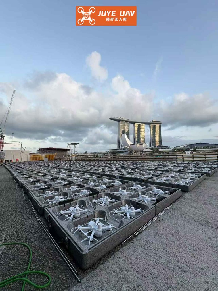
In practice, formation drone light shows often involve hundreds of drones, so scalability is key. The consensus algorithm is decentralized, meaning each drone only needs information from its neighbors, reducing communication overhead. For a large-scale formation drone light show, the communication topology can be designed as a spanning tree or a grid, and the algorithm parameters can be tuned for faster convergence. The table below summarizes recommended parameters for different scales of formation drone light shows.
| Show Scale (Number of Drones) | Recommended \(\gamma\) | Recommended \(\alpha\) | Max Communication Range (m) | Typical Convergence Time (s) |
|---|---|---|---|---|
| Small (5-20) | 20 | 1 | 50 | 10-100 |
| Medium (20-100) | 15 | 0.8 | 100 | 30-150 |
| Large (100-1000) | 10 | 0.5 | 200 | 60-300 |
These values are based on simulations and can be adjusted for specific formation drone light show requirements, such as faster transitions or tighter formations. The saturation bounds should also be set according to drone specifications; for example, consumer drones might have lower acceleration limits than professional ones. In a formation drone light show, it’s common to use identical drones to simplify parameter tuning, but the algorithm can handle heterogeneity by assigning different bounds per drone.
Another aspect of formation drone light shows is the need for real-time trajectory generation. The virtual reference point can follow a precomputed path, but in interactive shows, it might need to update dynamically based on audience input or sensor data. The consensus algorithm can incorporate time-varying formation offsets \(r_i^d(t)\) to create morphing shapes. For instance, to switch from a circle to a square, the offsets can be interpolated over time. The control law adapts naturally because the error terms include \(s^\star – s_i + r_i^I(t)\), where \(r_i^I(t) = C_{bI}(t) r_i^d(t)\). This flexibility is a major advantage for creative formation drone light shows.
To demonstrate the algorithm’s effectiveness in a dynamic scenario, consider a formation drone light show where drones must form a rotating star pattern. The virtual reference point moves in a circle: \(s^\star(t) = [R \cos(\omega t), R \sin(\omega t), h]^T\), with radius \(R = 10\) meters, angular rate \(\omega = 0.1\) rad/s, and altitude \(h = 50\) meters. The formation offsets \(r_i^d\) define a star shape that also rotates relative to the reference point, adding complexity. The constrained consensus algorithm ensures that drones track this moving formation without exceeding their speed limits. The maximum required speed for a drone at the edge of the formation can be estimated as \(v_{req} = R\omega + \omega \|r_i^d\|\), which must be below \(v_{max}\). If not, the saturation function will limit accelerations, causing the drones to lag slightly but maintain formation integrity. This is acceptable in many formation drone light shows, as the visual impact is preserved.
In terms of implementation, the control algorithm can run on each drone’s onboard processor or on a central computer that broadcasts commands. For decentralized formation drone light shows, onboard processing is preferred to avoid single points of failure. The computational cost is modest: each drone needs to compute sums over its neighbors, which scales linearly with neighborhood size. With modern microcontrollers, this is feasible even for complex formation drone light shows with high update rates (e.g., 50 Hz).
To summarize, the optimization of formation drone light shows through motion-constrained consensus algorithms offers significant benefits. By incorporating virtual reference points and saturation functions, we can achieve precise formation control that respects physical limits. The algorithm ensures asymptotic convergence to desired shapes, fast response times, and scalability to large fleets. For formation drone light show producers, this means more reliable and creative performances, with drones moving in perfect harmony. Future work could explore adaptive tuning of parameters based on real-time performance or integration with obstacle avoidance for outdoor shows. As drone technology advances, such algorithms will become even more critical for pushing the boundaries of formation drone light shows.
In conclusion, the synergy between consensus theory and formation drone light shows opens up new possibilities for aerial entertainment. The proposed approach addresses key challenges like motion constraints and formation accuracy, making it a valuable tool for designers and engineers. Whether for small-scale displays or massive spectacles, these optimized algorithms can help create unforgettable formation drone light shows that captivate audiences worldwide.