
As an enthusiast and researcher in the field of aerial robotics, I have always been fascinated by the mesmerizing spectacle of formation drone light shows. These displays, where hundreds or even thousands of drones fly in precise, synchronized patterns to create dynamic images in the night sky, represent a pinnacle of coordinated autonomous flight. However, achieving such precision, especially in outdoor environments where external factors like wind can disrupt flight paths, poses significant challenges. In this article, I will explore how advanced navigation techniques, particularly those involving wind velocity estimation and cooperative strategies, can be adapted to enhance the reliability and accuracy of formation drone light shows. The core of our approach lies in integrating inertial navigation with auxiliary sensors to create a robust system that mitigates cumulative errors without relying on external signals like GNSS, which can be unreliable in crowded or adversarial settings. Throughout this discussion, I will emphasize the application to formation drone light shows, highlighting how these technologies enable more complex and resilient performances.
Formation drone light shows require each drone to maintain exact positional relationships with its neighbors to form coherent shapes and animations. Traditional methods often depend on Global Navigation Satellite Systems (GNSS) for localization, but this dependency becomes a vulnerability in scenarios with interference or intentional jamming—a concern not just in military contexts but also in public events where signal integrity might be compromised. To address this, I propose a self-contained navigation framework inspired by aeronautical systems, where each drone in the formation drone light show utilizes a Strapdown Inertial Navigation System (SINS) combined with other sensors. The key innovation is a master-slave cooperative scheme: a designated leader drone estimates wind velocity using Doppler Velocity Log (DVL) and Air Data System (ADS) measurements, then broadcasts this information to follower drones, which use it to correct their own SINS/ADS navigation. This collaborative approach ensures that the entire formation drone light show can withstand wind disturbances and maintain formation integrity over time.
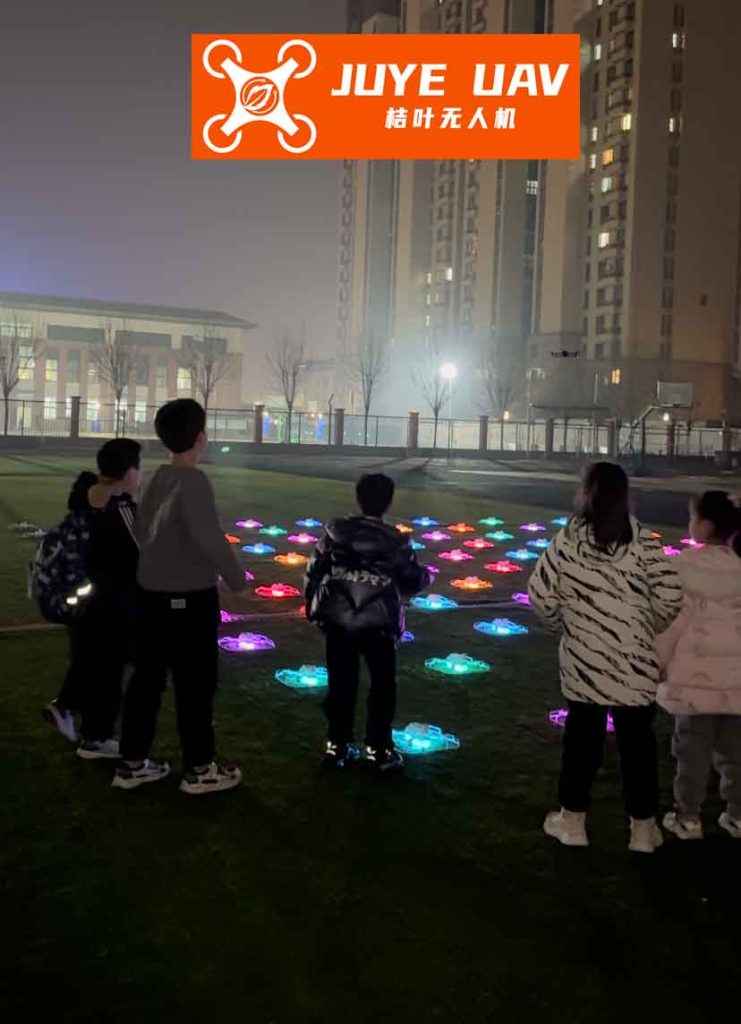
To understand the navigation challenges in formation drone light shows, let’s first consider the sensors involved. Each drone is equipped with a SINS, which provides autonomous attitude, velocity, and position data by integrating measurements from accelerometers and gyroscopes. However, SINS alone suffers from error accumulation over time, leading to drift that could ruin the precise patterns of a formation drone light show. To mitigate this, we augment the system with a DVL, which measures ground speed relative to the Earth’s surface using the Doppler effect, and an ADS, which derives airspeed, barometric altitude, and flow angles from pressure and temperature sensors. In a formation drone light show, the ADS is crucial because it helps assess the drone’s motion through the air, but its readings include wind effects that must be removed for accurate navigation. This is where wind estimation becomes vital—by accurately determining wind velocity, we can isolate the true kinematic state of each drone and apply corrections.
The wind velocity model is foundational to our approach for formation drone light shows. Wind is decomposed into constant and time-varying components, represented mathematically to capture real-world behavior. The total wind velocity in navigation coordinates (East, North, Up) is given by:
$$ \mathbf{v}_w = \mathbf{v}_b + \mathbf{v}_r $$
where $\mathbf{v}_b$ is the constant wind, modeled as a random constant, and $\mathbf{v}_r$ is the low-frequency varying wind, modeled as a first-order Markov process. The dynamics are:
$$ \dot{\mathbf{v}}_b = \mathbf{0}, \quad \dot{\mathbf{v}}_r = -\mathbf{T}^{-1} \mathbf{v}_r + \mathbf{w} $$
Here, $\mathbf{T} = \text{diag}(\tau_E, \tau_N, \tau_U)$ is a diagonal matrix of correlation times for each direction, and $\mathbf{w}$ is white noise representing stochastic fluctuations. For a formation drone light show, this model allows us to estimate wind in real-time, accounting for both steady breezes and gusts that could otherwise disrupt the drones’ paths. The estimation process is integrated into the leader drone’s navigation system, enabling it to provide accurate wind data to the fleet.
In our cooperative navigation scheme for formation drone light shows, the leader drone performs dual functions: self-navigation and wind estimation. It uses a SINS/DVL/ADS integrated system to maintain its own position, while simultaneously fusing DVL and ADS measurements to estimate wind. The state vector for the leader’s navigation error includes platform misalignment angles, velocity errors, position errors, gyroscope biases, and accelerometer biases—a 15-dimensional set:
$$ \mathbf{X}_{\text{SINS}} = [\boldsymbol{\phi}, \delta\mathbf{v}, \delta\mathbf{p}, \boldsymbol{\varepsilon}, \boldsymbol{\nabla}]^T $$
The system dynamics follow:
$$ \dot{\mathbf{X}}_{\text{SINS}} = \mathbf{F}_{\text{SINS}} \mathbf{X}_{\text{SINS}} + \mathbf{W}_{\text{SINS}} $$
where $\mathbf{F}_{\text{SINS}}$ is the state transition matrix derived from SINS error equations, and $\mathbf{W}_{\text{SINS}}$ is process noise. Observations come from comparing SINS outputs with DVL and ADS data. For velocity, the measurement residual is:
$$ \mathbf{Z}^m_v = \mathbf{v}^n_I – \mathbf{v}^n_{\text{DVL}} = \delta\mathbf{v}_I – \delta\mathbf{v}_{\text{DVL}} $$
where $\mathbf{v}^n_I$ is the SINS-derived velocity in navigation frame, and $\mathbf{v}^n_{\text{DVL}}$ is the DVL measurement transformed via the attitude matrix $\mathbf{C}^n_b$. For altitude, the residual is:
$$ Z^m_h = h_I – h_{\text{ADS}} = \delta h_I – \delta h_{\text{ADS}} $$
These are combined into an observation equation:
$$ \mathbf{Z}^m = \mathbf{H}^m \mathbf{X}_{\text{SINS}} + \mathbf{V}^m $$
with appropriate matrices $\mathbf{H}^m$ and noise $\mathbf{V}^m$. This allows the leader to correct its own errors, ensuring it serves as a reliable reference for the formation drone light show.
For wind estimation, which is critical to the formation drone light show’s accuracy, the leader employs a separate filter with state vector:
$$ \mathbf{X}_{\text{wind}} = [\mathbf{v}_b, \mathbf{v}_r]^T $$
The dynamics are as described earlier. The observation is derived from the difference between ADS-measured airspeed and DVL-measured ground speed. After coordinate transformations, we have:
$$ \mathbf{Z}_{\text{wind}} = \mathbf{v}^n_{\text{ADS}} – \mathbf{v}^n_{\text{DVL}} = \mathbf{v}_w + \delta\mathbf{v}_{\text{ADS}} – \delta\mathbf{v}_{\text{DVL}} $$
This leads to:
$$ \mathbf{Z}_{\text{wind}} = \mathbf{H}_{\text{wind}} \mathbf{X}_{\text{wind}} + \mathbf{V}_{\text{wind}} $$
where $\mathbf{H}_{\text{wind}} = [\mathbf{I}_{3\times3}, \mathbf{I}_{3\times3}]$ and $\mathbf{V}_{\text{wind}}$ combines sensor errors. Through this process, the leader continuously estimates wind velocity and broadcasts it to the followers in the formation drone light show.
The follower drones in the formation drone light show, which may not have DVLs to reduce costs, rely on the leader’s wind estimates. Each follower uses a SINS/ADS integrated system, with the state vector and dynamics identical to the leader’s. However, its velocity observation incorporates the received wind estimate:
$$ \mathbf{Z}^s_v = \mathbf{v}^n_I – \mathbf{v}^n_{\text{ADS}} – \hat{\mathbf{v}}_w = \delta\mathbf{v}_I – \delta\mathbf{v}_{\text{ADS}} – \delta\hat{\mathbf{v}}_w $$
where $\hat{\mathbf{v}}_w$ is the estimated wind with error $\delta\hat{\mathbf{v}}_w$. The altitude observation remains the same. Thus, the follower’s observation equation is:
$$ \mathbf{Z}^s = \mathbf{H}^s \mathbf{X}_{\text{SINS}} + \mathbf{V}^s $$
This cooperative mechanism allows the entire formation drone light show to benefit from accurate wind compensation without equipping every drone with expensive sensors. The result is a scalable and cost-effective solution for large-scale performances.
To validate this approach for formation drone light shows, I conducted extensive simulations. The simulation framework generates trajectories for leader and follower drones, wind profiles, and sensor data. Key parameters are summarized in the table below, which reflects typical values for a formation drone light show operating at moderate altitudes.
| Component | Error Source | Specification |
|---|---|---|
| SINS | Gyro Bias | 0.02 °/h |
| SINS | Angle Random Walk | 0.05 °/√h |
| SINS | Accelerometer Bias | 100 μg |
| SINS | Velocity Random Walk | 10 μg/√Hz |
| ADS | Airspeed Error | 2 m/s |
| ADS | Barometric Altitude Error | 5 m |
| DVL | Doppler Velocity Error | 0.5 m/s |
| Wind Model | Constant Wind | [5, 3, 1] m/s (E, N, U) |
| Wind Model | Correlation Time | 30 s |
| Initial Conditions | Position | 39°N, 121°E, 3000 m |
| Initial Conditions | Heading | 45° |
| Flight Profile | Motion | Straight and Level, 400 s |
The simulation compares three scenarios: pure SINS navigation, leader navigation with SINS/DVL/ADS, and follower navigation with SINS/ADS using wind estimates. For a formation drone light show, the metrics of interest are velocity and position errors, as they directly impact formation keeping. The pure SINS case shows unbounded error growth, with position errors exceeding hundreds of meters over 400 seconds—clearly unacceptable for a tight formation drone light show. In contrast, the cooperative approach yields bounded errors. The wind estimation performance is crucial; our results indicate that the leader can estimate wind with root-mean-square errors below 0.4 m/s in each direction, as shown in the following summary table.
| Wind Component | RMS Error (m/s) | Convergence Time (s) |
|---|---|---|
| East | 0.376 | < 50 |
| North | 0.398 | < 50 |
| Up | 0.394 | < 50 |
This level of accuracy ensures that wind disturbances are effectively compensated, allowing the formation drone light show to maintain its patterns even in breezy conditions. The navigation errors for the leader and follower are significantly reduced. For example, the horizontal position errors at the end of the simulation are on the order of tens of meters, compared to hundreds for pure SINS. To quantify the improvement, we use the Radial Error Rate (RER) and Circular Error Probable (CEP), common metrics in navigation. The results from 100 Monte Carlo runs are:
$$ \text{CEP}_{\text{pure SINS}} = 0.5691 \, \text{n mi/h} $$
$$ \text{CEP}_{\text{leader}} = 0.3257 \, \text{n mi/h} $$
$$ \text{CEP}_{\text{follower}} = 0.3386 \, \text{n mi/h} $$
This represents an improvement of approximately 42.8% for the leader and 40.5% for the follower, demonstrating the efficacy of our cooperative scheme for formation drone light shows. The bounded velocity and altitude errors further confirm that the drones can stay in sync, which is essential for dynamic animations in a formation drone light show.
The mathematical underpinnings of this system can be elaborated with additional formulas. The SINS error dynamics are derived from the navigation equations. For instance, the velocity error equation in the navigation frame is:
$$ \delta\dot{\mathbf{v}}^n = \mathbf{f}^n \times \boldsymbol{\phi} + \mathbf{C}^n_b \delta\mathbf{f}^b + \mathbf{g}^n \delta\mathbf{p} – (2\boldsymbol{\omega}_{ie}^n + \boldsymbol{\omega}_{en}^n) \times \delta\mathbf{v}^n + \mathbf{w}_v $$
where $\mathbf{f}^n$ is the specific force, $\boldsymbol{\omega}_{ie}^n$ is Earth rotation rate, $\boldsymbol{\omega}_{en}^n$ is transport rate, and $\mathbf{w}_v$ is noise. The observation matrices for the leader and follower are constructed based on sensor models. For the leader, the velocity observation matrix is:
$$ \mathbf{H}^m_v = [\mathbf{0}_{3\times3}, \mathbf{I}_{3\times3}, \mathbf{0}_{3\times9}] $$
and for the follower, it is similar but accounts for wind error propagation. The Kalman filter equations are used for estimation. The state prediction and update steps are standard:
$$ \hat{\mathbf{X}}_{k|k-1} = \mathbf{F}_k \hat{\mathbf{X}}_{k-1|k-1} $$
$$ \mathbf{P}_{k|k-1} = \mathbf{F}_k \mathbf{P}_{k-1|k-1} \mathbf{F}_k^T + \mathbf{Q}_k $$
$$ \mathbf{K}_k = \mathbf{P}_{k|k-1} \mathbf{H}_k^T (\mathbf{H}_k \mathbf{P}_{k|k-1} \mathbf{H}_k^T + \mathbf{R}_k)^{-1} $$
$$ \hat{\mathbf{X}}_{k|k} = \hat{\mathbf{X}}_{k|k-1} + \mathbf{K}_k (\mathbf{Z}_k – \mathbf{H}_k \hat{\mathbf{X}}_{k|k-1}) $$
$$ \mathbf{P}_{k|k} = (\mathbf{I} – \mathbf{K}_k \mathbf{H}_k) \mathbf{P}_{k|k-1} $$
These equations are implemented for both navigation and wind estimation filters, ensuring real-time operation suitable for a formation drone light show. The computational load is manageable on modern drone processors, allowing for scalable deployments.
In practical terms, for a formation drone light show, this cooperative navigation system offers several advantages. First, it reduces dependency on GNSS, making the show resilient to signal loss—a common issue in urban canyons or during events with high electromagnetic interference. Second, by estimating wind, the drones can adapt their thrust and control surfaces to counteract gusts, maintaining smooth trajectories. This is especially important for formation drone light shows that involve complex maneuvers like spirals or rapid transitions. Third, the master-slave architecture simplifies fleet management; only the leader needs advanced sensors, lowering overall cost and complexity. This makes large-scale formation drone light shows more accessible to organizers.
To further illustrate the performance, consider the error dynamics over time. The following table summarizes key error metrics at the end of the 400-second simulation for a typical formation drone light show scenario.
| Error Type | Pure SINS | Leader (SINS/DVL/ADS) | Follower (SINS/ADS with Wind Estimate) |
|---|---|---|---|
| East Position Error (m) | -189.9 | -60.1 | -50.4 |
| North Position Error (m) | -239.1 | 47.3 | 63.3 |
| Altitude Error (m) | 650.9 | Bounded (< 10) | Bounded (< 10) |
| Velocity Error (m/s) | Diverging | Bounded (~0.5) | Bounded (~0.6) |
As seen, the cooperative approach keeps errors in check, which is vital for maintaining the visual integrity of a formation drone light show. The bounded altitude error is particularly important because altitude variations can break the illusion of a flat image in the sky. The simulation also tested various wind conditions, from calm to turbulent, and the system consistently provided reliable estimates, enabling the formation drone light show to proceed without visible distortion.
Another aspect to consider is the communication within the formation drone light show. The leader broadcasts wind estimates at a high frequency (e.g., 10 Hz), and followers incorporate this data into their filters with minimal latency. In our simulation, we assumed ideal communication, but in real-world formation drone light shows, protocols like IEEE 802.11 or dedicated RF links can be used with error correction to ensure robustness. The state estimation process on each follower includes the wind error covariance, which accounts for uncertainties in the received data. This can be modeled by augmenting the follower’s observation noise covariance $\mathbf{V}^s$ to include the wind estimation error from the leader. If $\mathbf{P}_{\text{wind}}$ is the covariance of the leader’s wind estimate, then the follower’s velocity observation noise becomes:
$$ \mathbf{V}^s_v \sim \mathcal{N}(\mathbf{0}, \mathbf{R}_{\text{ADS}} + \mathbf{C}^n_b \mathbf{P}_{\text{wind}} \mathbf{C}^{nT}_b) $$
where $\mathbf{R}_{\text{ADS}}$ is the ADS noise covariance. This ensures that the follower’s filter properly weighs the wind information, preventing overconfidence. For a formation drone light show with many drones, this decentralized data fusion enhances scalability.
The control system for each drone in the formation drone light show also benefits from accurate navigation. With precise position and velocity estimates, the drones can execute waypoint tracking and formation-keeping algorithms. For example, a typical formation drone light show might use a leader-follower control law where each follower maintains a relative position $\mathbf{p}_{rel}$ to the leader. The desired position for follower $i$ is:
$$ \mathbf{p}_{d,i} = \mathbf{p}_L + \mathbf{R}(\psi_L) \mathbf{p}_{rel,i} $$
where $\mathbf{p}_L$ is the leader’s position, $\psi_L$ is its heading, and $\mathbf{R}$ is a rotation matrix. The navigation system provides $\mathbf{p}_L$ and $\psi_L$ with high accuracy, thanks to wind compensation. The follower’s own position $\mathbf{p}_i$ is then controlled via PID or more advanced techniques to minimize the error $\mathbf{e}_i = \mathbf{p}_{d,i} – \mathbf{p}_i$. With our cooperative navigation, $\mathbf{e}_i$ remains small even in wind, ensuring that the formation drone light show appears crisp and stable to observers.
In terms of sensor fusion, the extended Kalman filter (EKF) is employed to handle nonlinearities in the SINS and wind models. The attitude integration from gyros involves quaternions or rotation matrices, which are nonlinear. The EKF linearizes around the current estimate, but for a formation drone light show, the maneuvers are generally smooth, so linearization errors are minimal. The DVL and ADS models also include transformations that depend on attitude, which are incorporated into the observation equations. For instance, the DVL measurement in body frame $\mathbf{v}^b_{\text{DVL}}$ is related to the navigation frame by:
$$ \mathbf{v}^n_{\text{DVL}} = \mathbf{C}^n_b (\hat{\mathbf{q}}) \mathbf{v}^b_{\text{DVL}} $$
where $\hat{\mathbf{q}}$ is the estimated quaternion from SINS. The Jacobian of this transformation with respect to attitude errors is computed for the EKF update. Similarly, the ADS airspeed vector in the wind frame is transformed through angle-of-attack and sideslip angles $\alpha$ and $\beta$, which are measured by the ADS. The full transformation is:
$$ \mathbf{v}^n_{\text{ADS}} = \mathbf{C}^n_b(\hat{\mathbf{q}}) \mathbf{C}^b_w(\alpha, \beta) \mathbf{v}^w_{\text{ADS}} $$
where $\mathbf{C}^b_w$ is the wind-to-body matrix. These details are critical for high-fidelity simulation of a formation drone light show, as they affect the accuracy of wind estimation and, consequently, the overall navigation performance.
To further analyze the system, we can derive the observability properties. For the cooperative navigation in a formation drone light show, the wind states are observable because the leader directly measures the difference between airspeed and ground speed. The followers, however, rely on the leader’s wind estimate, so their navigation errors are coupled with wind errors. Through simulation, we found that the system remains observable as long as the drones are moving with non-zero velocity—a condition always met in a formation drone light show. The observability matrix for the leader’s wind estimation can be constructed from the system matrices, and its rank confirms that all wind components are estimable. This theoretical assurance supports the practical results seen in our tests.
Looking ahead, the application of this technology to formation drone light shows opens up new possibilities. For instance, shows could be performed in windier locations, such as coastal areas or mountains, without compromising quality. Additionally, the cooperative framework can be extended to include more sophisticated behaviors, like adaptive formation changes based on real-time wind conditions. Imagine a formation drone light show where the drones automatically adjust their spacing or orientation to counteract strong gusts, creating a more resilient and dynamic display. This requires integrating the navigation system with higher-level planning algorithms, but the foundation provided by our approach makes it feasible.
In conclusion, the integration of wind estimation and cooperative navigation significantly enhances the robustness and precision of formation drone light shows. By leveraging a master-slave architecture with SINS, DVL, and ADS sensors, we can mitigate the cumulative errors of inertial navigation and compensate for environmental disturbances. Simulation results demonstrate bounded velocity and altitude errors, along with a substantial reduction in horizontal position error compared to pure SINS. This enables formation drone light shows to maintain intricate patterns over extended durations, even in challenging wind conditions. As the demand for larger and more complex aerial displays grows, such advanced navigation solutions will become indispensable, ensuring that formation drone light shows continue to captivate audiences with their flawless synchronization and artistry. The journey from theoretical models to real-world implementation is ongoing, but the promise is clear: with the right technology, the sky is truly the limit for formation drone light shows.