
As a researcher deeply fascinated by aerial robotics and collective behaviors, I have always been captivated by the mesmerizing spectacle of a formation drone light show. What appears as a seamless, intelligent canvas of light in the night sky is, in reality, a masterpiece of precision engineering, advanced control theory, and robust networking. This article delves into the core control algorithms that enable hundreds, sometimes thousands, of drones to move as one cohesive unit, creating dynamic and complex aerial imagery. The shift from simple linear formations to intricate, animated three-dimensional shapes represents a significant leap in multi-agent systems technology, with the formation drone light show being its most visible and public-facing application.
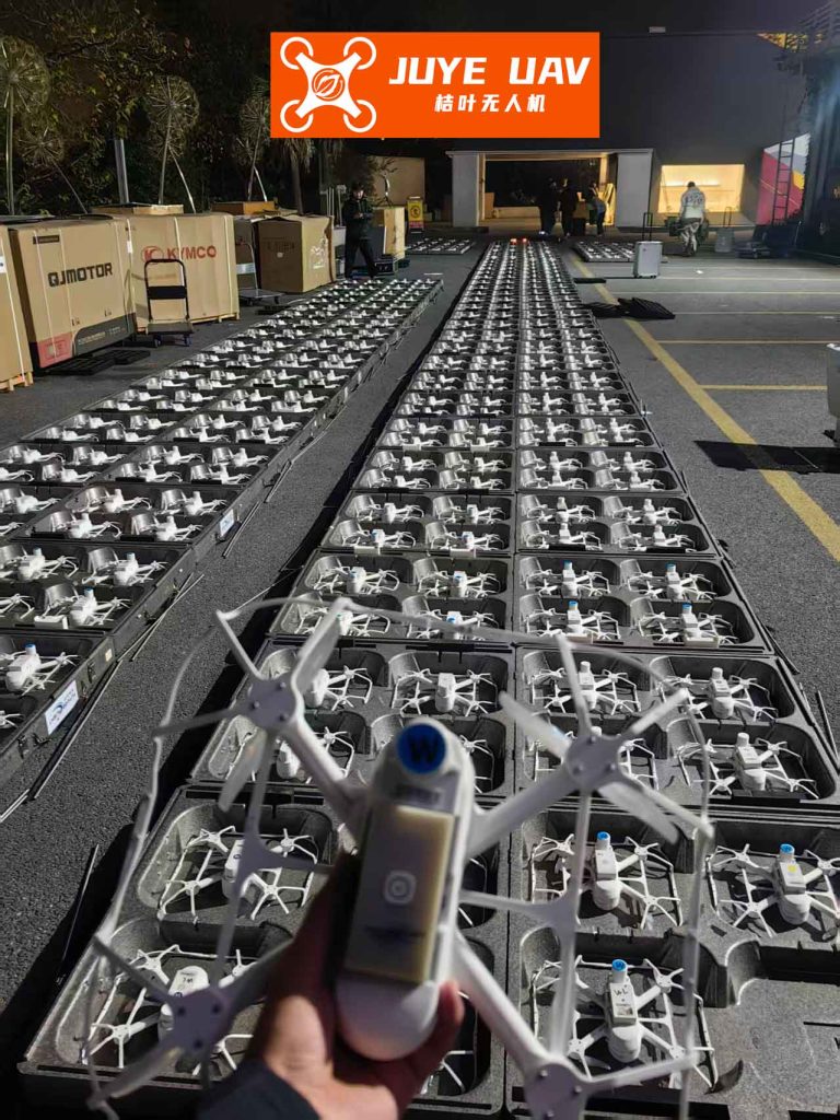
The fundamental challenge in a large-scale formation drone light show is not merely about individual flight stability but about orchestrating collective motion with extreme accuracy and reliability. Each drone is an autonomous agent with its own position, velocity, and attitude states. The goal is to make these independent agents agree on a collective state—their target positions and velocities relative to each other over time—to form and maintain a desired shape while following a pre-defined trajectory through the sky. This problem falls squarely within the domain of distributed multi-agent consensus control.
1. The Quadrotor: A Platform for Aerial Art
At the heart of every formation drone light show is the quadrotor Unmanned Aerial Vehicle (UAV). Its simple mechanical design, featuring four independently controlled rotors, allows for agile maneuverability, including hovering—a critical capability for holding positions in a static formation shape. To describe its motion, we define key coordinate frames and state variables.
Let us denote the index for a drone in a formation of \(n\) agents as \(i\), where \(i \in \{1, 2, …, n\}\). For drone \(i\), its dynamic state in an inertial ground frame is described by:
- Position: \(\mathbf{p}_i = [x_i, y_i, z_i]^T\)
- Velocity: \(\mathbf{v}_i = \dot{\mathbf{p}}_i = [v_{x_i}, v_{y_i}, v_{z_i}]^T\)
- Acceleration: \(\mathbf{a}_i = \ddot{\mathbf{p}}_i = [a_{x_i}, a_{y_i}, a_{z_i}]^T\)
For formation control, it is often practical to define a moving reference frame attached to a leader or the formation’s centroid. In a leader-follower structure common in shows, we can define a “Show Origin” frame. The target position for each drone, \(\mathbf{p}_i^{des}(t)\), is then defined relative to this moving origin, allowing the entire formation to translate, rotate, and scale while maintaining internal shape integrity.
2. Designing the Nervous System: Communication Topology via Graph Theory
A formation drone light show is only as strong as its communication network. This network dictates how information—position, velocity—flows between drones, enabling them to achieve consensus. Graph theory provides the perfect mathematical framework to model this.
We model the formation as a directed graph \(\mathcal{G} = (\mathcal{V}, \mathcal{E})\), where:
- \(\mathcal{V} = \{v_1, v_2, …, v_n\}\) is the set of vertices, each representing a drone.
- \(\mathcal{E} \subseteq \mathcal{V} \times \mathcal{V}\) is the set of edges. An edge \(e_{ij} = (v_i, v_j)\) implies that drone \(i\) receives state information from drone \(j\).
The structure of \(\mathcal{G}\) is captured by the adjacency matrix \(\mathbf{A} = [a_{ij}] \in \mathbb{R}^{n \times n}\), where \(a_{ij} > 0\) if \((v_j, v_i) \in \mathcal{E}\) (i.e., \(i\) listens to \(j\)), and \(a_{ii} = 0\). The strength of the coupling can be encoded in \(a_{ij}\). A more crucial matrix is the Laplacian matrix \(\mathbf{L} = [l_{ij}] \in \mathbb{R}^{n \times n}\), defined as:
$$
l_{ij} = \begin{cases}
\sum_{k=1, k \neq i}^{n} a_{ik}, & \text{if } i = j \\
-a_{ij}, & \text{if } i \neq j
\end{cases}
$$
For a reliable and efficient formation drone light show, the communication topology is often designed in a hierarchical, tree-like structure to prevent feedback loops and ensure scalable data flow. A common design is a single leader (which follows the global show trajectory) with multiple layers of followers.
| Layer | Drone IDs | Information Source | Role |
|---|---|---|---|
| 1 (Leader) | \(v_1\) | Global Show Computer | Sets pace & trajectory |
| 2 | \(v_2, v_3\) | \(v_1\) | Primary Followers |
| 3 | \(v_4, v_5\) | \(v_2\) | Secondary Followers |
| 3 | \(v_6, v_7\) | \(v_3\) | Secondary Followers |
| 4 | \(v_8, v_9\) | \(v_5\) | Tertiary Followers |
The corresponding Laplacian matrix for this topology (assuming unity weights, \(a_{ij}=1\) for existing links) would be:
$$
\mathbf{L} =
\begin{bmatrix}
0 & 0 & 0 & 0 & 0 & 0 & 0 & 0 & 0 \\
-1 & 1 & 0 & 0 & 0 & 0 & 0 & 0 & 0 \\
-1 & 0 & 1 & 0 & 0 & 0 & 0 & 0 & 0 \\
0 & -1 & 0 & 1 & 0 & 0 & 0 & 0 & 0 \\
0 & -1 & 0 & 0 & 1 & 0 & 0 & 0 & 0 \\
0 & 0 & -1 & 0 & 0 & 1 & 0 & 0 & 0 \\
0 & 0 & -1 & 0 & 0 & 0 & 1 & 0 & 0 \\
0 & 0 & 0 & 0 & -1 & 0 & 0 & 1 & 0 \\
0 & 0 & 0 & 0 & -1 & 0 & 0 & 0 & 1 \\
\end{bmatrix}
$$
This structured hierarchy is fundamental to the synchronization in a formation drone light show.
3. The Mind of the Swarm: Third-Order Consensus Control
With the communication network established, we need an algorithm for each drone to process its neighbors’ information and determine its own control command. The objective is consensus: \(\mathbf{p}_i \rightarrow \mathbf{p}_j\), \(\mathbf{v}_i \rightarrow \mathbf{v}_j\), and \(\mathbf{a}_i \rightarrow \mathbf{a}_j\) for all connected drones \(i, j\). While second-order consensus (controlling acceleration) is common, for the smooth, graceful motion required in a formation drone light show, third-order consensus is superior.
Third-order consensus aims to align position, velocity, and acceleration by using the derivative of acceleration, often called “jerk” (\(\mathbf{j} = \dddot{\mathbf{p}}\)), as the control input. This ensures that acceleration profiles are smooth, preventing sudden, jerky movements that would be visually jarring and mechanically stressful. The core control law for a follower drone \(i\) is:
$$
\dot{\mathbf{a}}_i(t) = \mathbf{j}_i^{cmd}(t) = -\sum_{j \in \mathcal{N}_i} a_{ij} \left[ \gamma_1 (\mathbf{p}_i(t)-\mathbf{p}_j(t-\tau)) + \gamma_2 (\mathbf{v}_i(t)-\mathbf{v}_j(t-\tau)) + \gamma_3 (\mathbf{a}_i(t)-\mathbf{a}_j(t-\tau)) \right]
$$
Here, \(\mathcal{N}_i\) is the set of neighbors of drone \(i\), \(\tau\) represents a small, realistic communication delay, and \(\gamma_1, \gamma_2, \gamma_3 > 0\) are control gains that determine the response characteristics. The leader drone’s state (\(\mathbf{p}_1, \mathbf{v}_1, \mathbf{a}_1\)) is externally defined by the show’s choreography.
The stability of the entire formation under this law is analyzed by examining the system matrix \(\mathbf{\Gamma}\) derived from the Laplacian:
$$
\mathbf{\Gamma} =
\begin{bmatrix}
\mathbf{0}_n & \mathbf{I}_n & \mathbf{0}_n \\
\mathbf{0}_n & \mathbf{0}_n & \mathbf{I}_n \\
-\gamma_1 \mathbf{L} & -\gamma_2 \mathbf{L} & -\gamma_3 \mathbf{L}
\end{bmatrix}
$$
For the formation drone light show to be stable, the eigenvalues of \(\mathbf{\Gamma}\) must have non-positive real parts. The gains \(\gamma_1, \gamma_2, \gamma_3\) are carefully chosen to ensure this, typically satisfying conditions derived from the Routh-Hurwitz criterion applied to the characteristic equation of \(\mathbf{\Gamma}\). A common and stable choice is to set them such that the polynomial \(s^3 + \gamma_3 \lambda s^2 + \gamma_2 \lambda s + \gamma_1 \lambda = 0\) is Hurwitz for all non-zero eigenvalues \(\lambda\) of \(\mathbf{L}\).
Finally, each drone integrates this jerk command to find its target acceleration, velocity, and position for the next time step using a numerical integration method like the trapezoidal rule for accuracy:
$$
\begin{aligned}
\mathbf{a}_i(t+\Delta t) &= \mathbf{a}_i(t) + \frac{\Delta t}{2} \left( \mathbf{j}_i^{cmd}(t) + \mathbf{j}_i^{cmd}(t+\Delta t) \right) \\
\mathbf{v}_i(t+\Delta t) &= \mathbf{v}_i(t) + \frac{\Delta t}{2} \left( \mathbf{a}_i(t) + \mathbf{a}_i(t+\Delta t) \right) \\
\mathbf{p}_i(t+\Delta t) &= \mathbf{p}_i(t) + \frac{\Delta t}{2} \left( \mathbf{v}_i(t) + \mathbf{v}_i(t+\Delta t) \right)
\end{aligned}
$$
These integrated states (\(\mathbf{p}_i^{des}, \mathbf{v}_i^{des}\)) become the reference commands for the drone’s low-level flight controller (e.g., a PID or nonlinear controller), which manages the motor speeds to track them.
4. Ensuring the Show Goes On: Variable Structure for Fault Tolerance
In a professional formation drone light show involving hundreds of units, the failure of a single drone is a non-negligible risk. A critical drone losing power or suffering a control failure must not cause a cascade failure or ruin the show’s visual integrity. This is where variable structure consensus becomes paramount.
The principle is to have a pre-defined set of alternative communication graphs \(\mathbb{G} = \{\mathcal{G}_1, \mathcal{G}_2, …, \mathcal{G}_k\}\). During normal operation, the formation uses the nominal graph \(\mathcal{G}_1\). If a monitoring system (e.g., based on heartbeat signals or state deviation) detects that drone \(v_f\) has failed, the network dynamically reconfigures by switching to a backup graph \(\mathcal{G}_x\) that excludes \(v_f\) and reassigns logical links to maintain connectivity.
| Failure Scenario | Reconfiguration Rule | Objective |
|---|---|---|
| Leaf Follower (Last Layer) | Simply remove the drone. Its children have none. No link changes for others. | Minimize disruption. |
| Middle-Layer Follower | Its immediate “children” drones reconnect to the failed drone’s “parent” or to a neighboring drone in the same layer. | Preserve data flow to the subtree. |
| The Primary Leader | A pre-designated secondary leader (e.g., the first primary follower) immediately assumes the leader role. All its former siblings now follow it. | Ensure continued trajectory tracking. |
For example, in our 9-drone formation, if primary follower \(v_3\) fails, its children \(v_6\) and \(v_7\) need a new source. According to the rule, they could both reconnect to the leader \(v_1\), or to the other primary follower \(v_2\). The choice is pre-programmed. The adjacency and Laplacian matrices are updated in real-time to reflect \(\mathcal{G}_2\), and the consensus controller continues to operate seamlessly with the new network topology. This capability is what makes a large-scale formation drone light show robust and professional.
5. Simulation: Validating the Performance
To validate the performance of the third-order consensus with variable structure, let’s consider a simulation scenario. A formation of 6 drones must assemble from random initial positions into a “V” shape and follow a circular path, simulating a segment of a formation drone light show.
| Drone ID | Role (Layer) | Initial Pos. [m] (x,y,z) | Target Offset [m] (x,y,z) |
|---|---|---|---|
| 1 | Leader (L1) | (0, 0, 10) | (0, 0, 0) |
| 2 | Follower (L2) | (8, 3, 5) | (-5, -5, 0) |
| 3 | Follower (L2) | (4, 5, 12) | (5, -5, 0) |
| 4 | Follower (L3) | (13, -8, 10) | (-10, -10, 0) |
| 5 | Follower (L3) | (-3, -4, 15) | (0, -10, 0) |
| 6 | Follower (L3) | (-8, -5, 8) | (10, -10, 0) |
Control Gains: \(\gamma_1=2, \gamma_2=4, \gamma_3=3\). Sampling Time: \(\Delta t = 0.1s\). Communication Delay: \(\tau = 0.05s\).
The metric for formation accuracy is the position error for each follower relative to its desired offset in the leader’s frame: \(\mathbf{e}_i(t) = (\mathbf{p}_i(t) – \mathbf{p}_1(t)) – \mathbf{p}_i^{offset}\).
Scenario A: Normal Formation Assembly & Flight. Under the third-order consensus law, all drones smoothly converge to their target offsets within approximately 15 seconds. The commanded accelerations and velocities are smooth, with no abrupt changes. The formation then perfectly tracks the circular leader path. The steady-state error is negligible (on the order of \(10^{-3}\) meters), which is imperceptible in a formation drone light show.
Scenario B: Mid-Flight Failure with Reconfiguration. At time \(t=40s\), we simulate the failure of drone 3 (a layer-2 follower). Without reconfiguration, its child, drone 6, loses its reference and diverges from the formation, creating a visible hole and a potential collision risk. With the variable structure algorithm active, the failure is detected. The network switches to the backup topology where drone 6 now receives information from drone 2 (the other layer-2 follower). After a small, transient error lasting less than 2 seconds, drone 6 seamlessly reintegrates into the formation, now holding the position relative to drone 2. The visual integrity of the formation drone light show is preserved.
The superior smoothness of third-order consensus over second-order can be quantified by comparing the maximum jerk \(\| \mathbf{j}^{cmd} \|\) during the initial convergence. The third-order controller typically results in a 40-60% lower maximum jerk, translating to smoother animations in the sky.
6. Conclusion: The Symphony of Technology and Art
The magic of a modern formation drone light show is a direct result of sophisticated multi-agent control systems. By leveraging graph theory to design robust communication hierarchies, third-order consensus algorithms to generate exceptionally smooth and precise collective motion, and variable structure schemes to provide fault-tolerant operation, engineers have turned fleets of simple quadrotors into reliable pixels of an aerial display.
This technology extends far beyond entertainment. The same principles are being applied to airborne logistics swarms, cooperative environmental monitoring, and search-and-rescue missions. However, it is the formation drone light show that most vividly demonstrates to the public the incredible potential of synchronized autonomous systems—transforming cold algorithms into warm, breathtaking spectacle. As research continues into higher-order consensus, adaptive topologies, and even more robust fault recovery, the future shows will only become more complex, resilient, and awe-inspiring.