
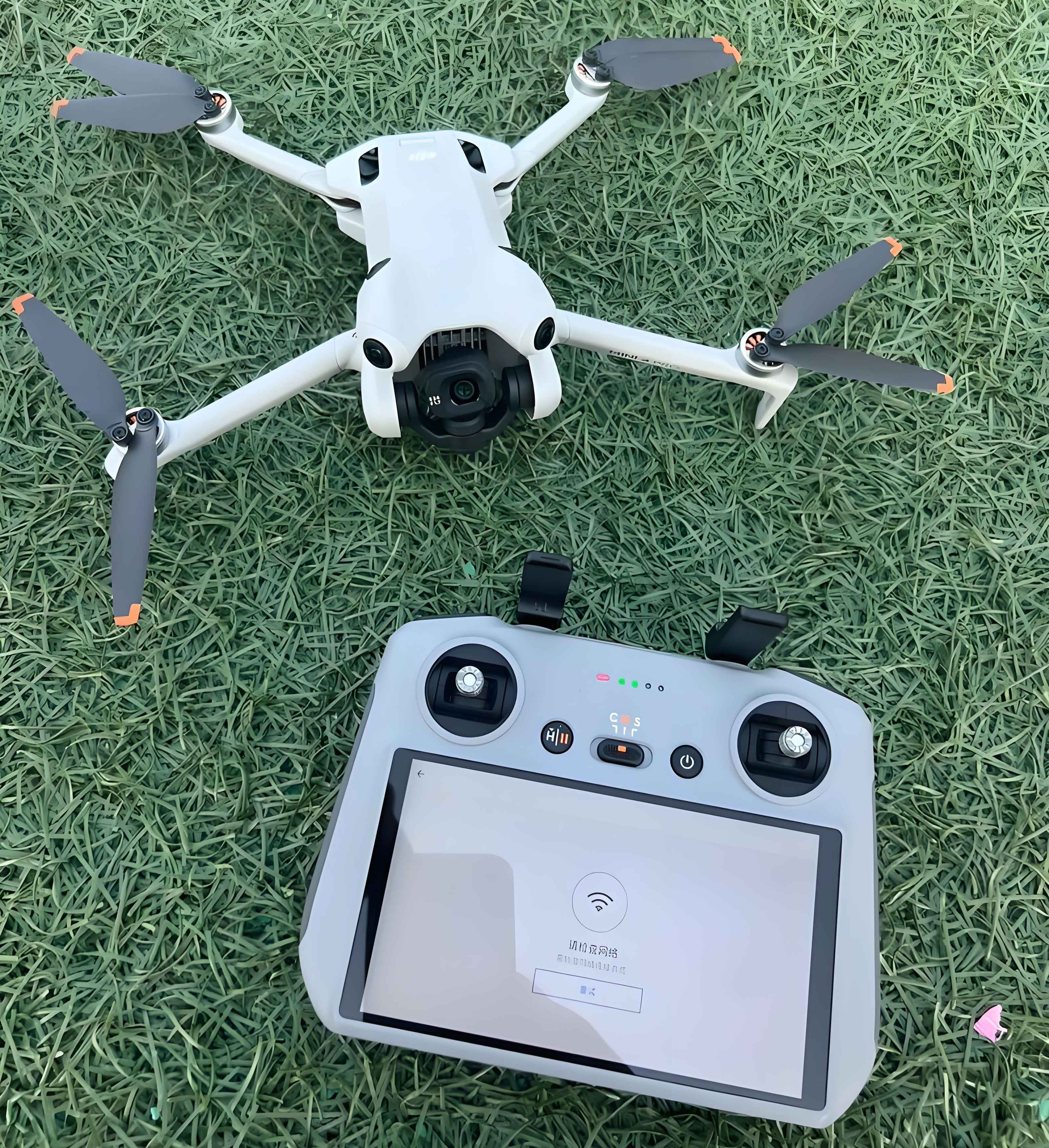
The conceptual foundation of camera drone technology originates from the “God’s Eye View” principle, enabling unique visual perspectives through aerial imaging. Modern camera UAVs leverage vertical takeoff/landing and precision hovering capabilities for applications including power line inspection, meteorological monitoring, and cinematography. This project implements a quadcopter-based aerial imaging system integrating real-time video transmission for ground station monitoring.
System Architecture
The aerial imaging platform comprises five core subsystems:
| Subsystem | Components |
|---|---|
| Propulsion | 3S Li-Po battery (4200mAh), 20A ESCs, A2212-9 brushless motors (1400KV), 8045 propellers |
| Control | DJI NAZA V2 flight controller with power module |
| Communication | 7-channel transmitter/receiver system |
| Imaging | Chuangxinke 5.8GHz wireless video system (48 channels, 70mA @12V) |
| Airframe | F330 carbon fiber frame with protective ring and damping landing gear |
Aerodynamic Principles
As an underactuated system with four control inputs and six degrees of freedom, the camera UAV’s motion follows these governing equations:
Hover Condition:
$$\sum_{i=1}^{4} F_i = mg$$
where $F_i$ = lift force per rotor, $m$ = UAV mass, $g$ = gravitational acceleration
Pitch/Roll Dynamics:
$$\tau_{\theta,\phi} = k_m \begin{pmatrix} 0 & -l & 0 & l \\ -l & 0 & l & 0 \end{pmatrix} \begin{pmatrix} \omega_1^2 \\ \omega_2^2 \\ \omega_3^2 \\ \omega_4^2 \end{pmatrix}$$
where $\tau$ = torque, $k_m$ = motor constant, $l$ = arm length, $\omega_i$ = motor angular velocities
Yaw Control:
$$\tau_{\psi} = k_d (\omega_1^2 + \omega_3^2 – \omega_2^2 – \omega_4^2)$$
where $k_d$ = drag coefficient, counter-rotating pairs (1,3) and (2,4)
Translational Motion:
$$F_{horizontal} = \left( \sum_{i=1}^{4} F_i \right) \sin \theta$$
with $\theta$ = tilt angle induced by differential thrust
Innovation Framework
| Domain | Advancement |
|---|---|
| Safety | Carbon fiber protective ring prevents propeller contact injuries; Damped landing gear absorbs impact energy |
| Autonomy | Fail-safe protocols: Auto-landing at low battery; Return-to-home on signal loss |
| Imaging System | Wireless 5.8GHz video transmission; Gimbal-free adjustable camera mounting |
Integration & Calibration
Assembly follows a sequential process: Power distribution board soldering → Frame assembly → Motor/ESC mounting → Flight controller installation → Camera integration. Critical calibration steps include:
- Transmitter-receiver binding and channel calibration
- ESC throttle calibration sequence:
- Max throttle during power-on → Two beeps
- Min throttle → Three beeps + confirmation tone
- Motor rotation verification:
- Motors 1 & 3: Counter-clockwise
- Motors 2 & 4: Clockwise
- Flight controller parameter tuning (initial sensitivity: 80-90%)
Flight Performance Metrics
| Parameter | Value | Condition |
|---|---|---|
| Hover Stability | ±0.2m position hold | Indoor (5×5×3m net enclosure) |
| Video Latency | <150ms | 100m transmission range |
| Endurance | 15 minutes | With imaging payload |
Concluding Analysis
This camera drone implementation demonstrates effective integration of commercial components into a functional aerial imaging platform. The F330-based solution achieves competitive performance metrics at low cost while maintaining compact dimensions (330mm wheelbase). Future enhancements will focus on improving positional accuracy through RTK-GPS integration and extending operational endurance via hybrid power systems. The developed camera UAV framework provides a foundation for specialized applications in industrial inspection and surveillance domains.