
In the domain of modern warfare, the Command and Control (C2) system stands as the operational nucleus of a military UAV, directly dictating mission success and overall combat effectiveness. Throughout my career designing these complex systems, I have observed a persistent trend: the design of the human-machine interface often becomes an afterthought, a passive layer built upon established hardware and software architectures. This leads to cluttered displays, convoluted control schemes, and an overwhelming proliferation of parameters, forcing the operator—the human in the loop—to adapt to the machine’s limitations. This approach is fundamentally flawed. My design philosophy, and the core of the process I advocate for, is rooted in Human-Centered Design (HCD). This paradigm insists that the design of any system must begin and end with the human operator’s needs, cognitive capabilities, and physical characteristics. It is not about the technology itself, but about how the technology serves the human to achieve superior performance. For a military UAV C2 system, this means designing an interface that transforms data into comprehension, reduces cognitive load under stress, and enables swift, decisive action. The following outlines the comprehensive, iterative design process we employ to achieve this goal.
The foundation of our entire endeavor is the HCD philosophy. It is a structured approach that places the user—the UAV operator, mission commander, or sensor specialist—at the forefront of every design decision. We start by understanding the user’s tasks, operational environment (both physical and informational), and potential stressors. The process is inherently iterative, relying on prototyping and evaluation with representative users to refine the design continuously. The ultimate aim is to create an intuitive, efficient, and resilient interaction system where the machine’s capabilities are seamlessly extended through the human’s judgment and creativity. This is not merely about usability; for a military UAV system, it is about survivability, mission accomplishment, and reducing the potential for catastrophic human error.
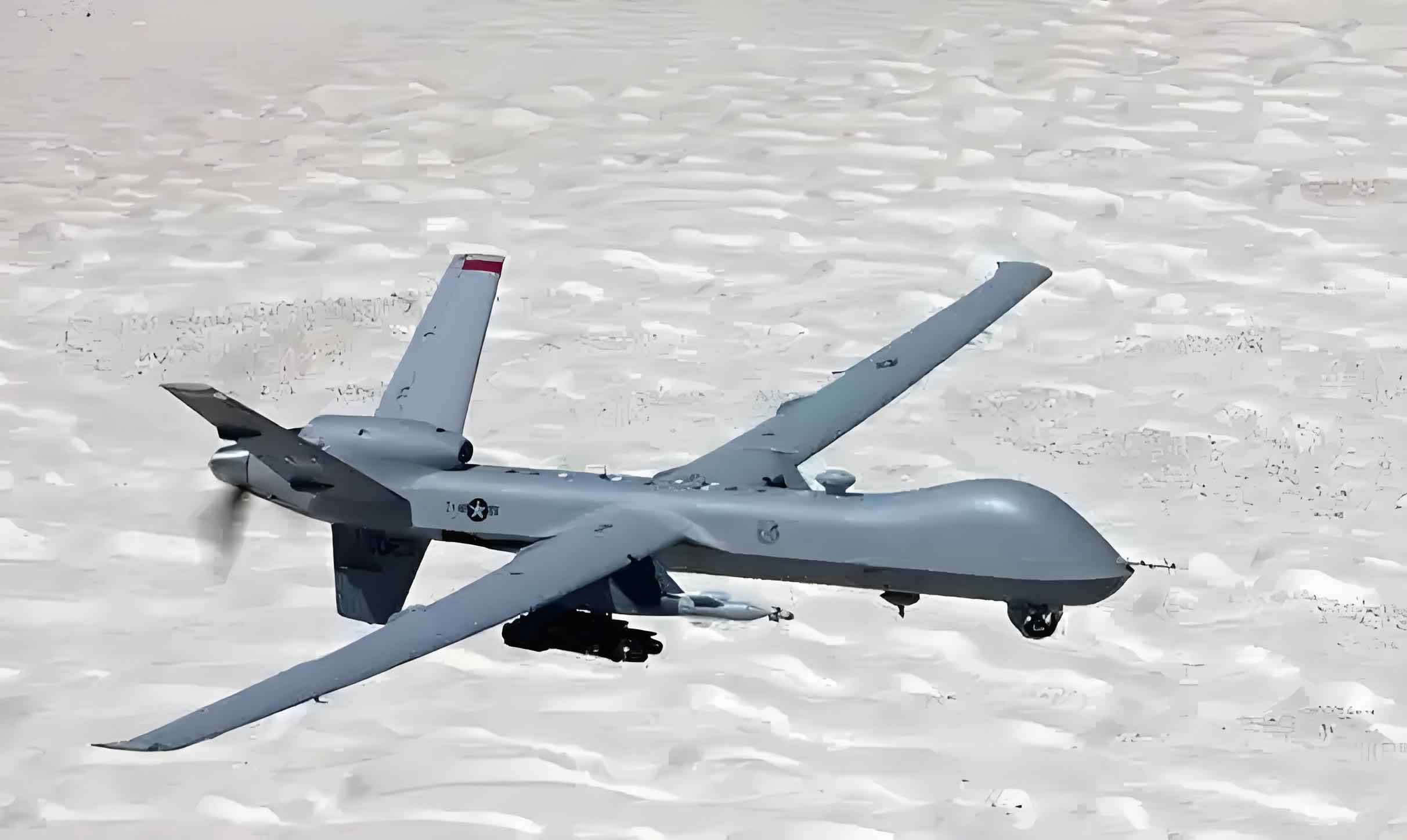
The design of a military UAV C2 system presents unique challenges that distinguish it from commercial or consumer applications. The operator is not merely “using” a tool; they are managing a complex, dynamic, and often high-stakes battlespace. Key challenges include:
- Situation Awareness (SA) Maintenance: The operator must build and maintain a high-fidelity mental model of the UAV’s status, location, payload, fuel state, and the surrounding environment (terrain, weather, threats, allies). The interface must integrate and present this multi-dimensional data coherently.
- High Cognitive Workload: Operators frequently manage multiple UAVs simultaneously (controlling one while monitoring others), analyze sensor feeds, communicate with other assets, and make time-critical decisions. The design must mitigate, not contribute to, cognitive overload.
- Stress and Fatigue: Missions can last for many hours. The interface must remain legible, predictable, and error-tolerant even when the operator is fatigued.
- Rapid Decision-Making: In contested environments, seconds matter. Controls must be logical, displays must highlight critical information, and mode transitions must be clear and unambiguous.
Addressing these challenges requires a disciplined, phase-gated design process.
The Human-Machine Interaction Design Process
Based on standard systems engineering practices, the HMI design process is an integrated thread within the larger development cycle. Our tailored process for military UAV C2 systems consists of several interconnected phases, as shown in the model below:
$$ \text{HCI-IMP} = \sum_{i=1}^{n} [R(A_i) + CD_i + PD_i + DD_i] \rightarrow P_i \xrightarrow[\text{Validation}]{\text{Evaluation}} O_i $$
Where HCI-IMP is the Human-Computer Interaction Implementation Maturity, resulting from the iterative sum of phases: Requirements (R) based on Activity Analysis (A), Conceptual Design (CD), Preliminary Design (PD), Detailed Design (DD), leading to a Prototype (P), which undergoes Evaluation & Validation, resulting in an Optimized design (O) for iteration *i*.
The subsequent sections detail each of these phases.
Phase 1: Requirements Capture & Analysis
This initial phase is critical for moving from vague notions to concrete, actionable design inputs. We actively seek out needs from all stakeholders, understanding that the “user” is not a monolith.
1.1 Requirements Capture: We employ multiple techniques to gather a 360-degree view of needs.
| Capture Method | Focus & Source | Key Artifacts/Outputs |
|---|---|---|
| Contextual Inquiry | Observing operators in their actual or simulated work environment. Understanding workflows, pain points, and informal workarounds. | Field notes, video recordings, workflow diagrams. |
| Product & Document Analysis | Analyzing system specifications, operational concepts (CONOPS), emergency procedures, functional requirements, and interface control documents. | List of mandated functions, data exchange requirements, regulatory constraints. |
| Stakeholder Interviews | Structured conversations with pilots, sensor operators, intelligence analysts, maintainers, and acquisition officials. We listen for explicit needs and latent desires. | Interview transcripts, identified user personas, scenario descriptions. |
| Questionnaires & Surveys | Quantifying preferences, workload perceptions, and satisfaction with existing systems across a larger population. | Statistical data on user preferences and priority rankings. |
1.2 Requirements Analysis: The raw captured data is then synthesized and structured.
- Requirement Identification & Categorization: Separating functional needs (e.g., “the system shall display fuel state”) from non-functional HMI needs (e.g., “fuel state shall be perceivable within 2 seconds with 99% accuracy under all lighting conditions”).
- System & Operational Goal Definition: Establishing top-level objectives (e.g., “enable single-operator control of four armed reconnaissance UAVs”).
- Task Analysis: Breaking down high-level missions into discrete, sequential tasks and actions. This often involves creating Hierarchical Task Analysis (HTA) diagrams.
- Functional Analysis: Decomposing system capabilities into atomic functions. This creates a function list that will later be allocated to human, machine, or shared control.
The output is a validated HMI Requirements Specification, which serves as the baseline for all subsequent design work.
Phase 2: Conceptual Design
Here, we translate requirements into the first visions of the system’s interaction landscape. It’s about defining the “big picture” before getting lost in details.
2.1 Interaction Framework Design: We establish the overarching structure. Will the interface be organized around the mission timeline, geographical space, vehicle status, or a hybrid? This defines the primary navigation metaphor and mental model we impart to the operator.
2.2 Interaction Mode Design: We select the fundamental paradigms for user input and system feedback. For a military UAV system, this is typically a blend:
- Activity-Based Interaction: The user initiates a high-level command (e.g., “Perform Area Search”), and the system executes a complex sequence.
- Object-Based Interaction: The user directly manipulates entities on the map (e.g., a UAV icon, a target symbol, a sensor footprint).
The choice of modes directly impacts the user’s sense of control and agency. The balance is captured by the Control-Autonomy Ratio (CAR):
$$ CAR = \frac{\sum (\text{Manual Command Interventions})}{\sum (\text{Automated System Actions})} $$
We design to optimize this ratio for different mission phases.
2.3 Information Architecture Design: We define the types, criticality, and relationships of information that must flow between human and machine. This involves categorizing data (e.g., navigation, payload, communication, system health) and assigning priority levels (e.g., critical alert, status update, log information).
2.4 Sketching & Storyboarding: Low-fidelity sketches and storyboards are created to visualize scenarios. These quick, disposable artifacts communicate ideas for screen layouts, control groupings, and interaction sequences without investment in detailed graphics. They are essential for early team and stakeholder alignment.
Phase 3: Preliminary Design
This phase focuses on allocating responsibilities and defining the human’s specific role within the system.
3.1 Function Allocation: Using the function list from analysis, we apply formal allocation principles (e.g., Fitts’ List) to decide whether a function is best performed by the human, the machine, or through collaboration.
| Allocation Principle | Bias Towards Human | Bias Towards Machine (Automation) |
|---|---|---|
| Superior Ability | Pattern recognition, adaptation, judgment in novel situations. | High-speed computation, precise repetition, force output. |
| Mandatory Allocation | Ethical decisions (e.g., weapon release authorization). | Functions exceeding human physiological limits (e.g., millisecond-level flight stabilization). |
| Balance of Load & Competence | To maintain operator SA and engagement. | To reduce repetitive, low-level tasks and fatigue. |
3.2 Job & Task Design: For functions allocated to the human or shared via the interface, we perform a detailed task analysis.
- Operational Sequence Diagram (OSD): We map out the precise steps, decisions, and system responses for critical tasks like target handoff or emergency landing.
- Job Design: We determine the number of operator stations, the roles (e.g., Air Vehicle Operator, Mission Payload Operator), and how tasks are distributed among them to balance workload. The goal is to define clear, coherent, and sustainable jobs.
The output is a Task Analysis Report and Job Specification, which explicitly list every action the operator must perform and the information required for each.
Phase 4: Detailed Design
Here, the abstract tasks and functions materialize into concrete interface elements. This encompasses both physical (hardware) and virtual (software) components.
4.1 Display Design: We select modalities and design specific displays.
- Visual Displays: Choosing between heads-down multi-function displays, head-up displays, or large-area situational displays. We define symbology, color coding (military standards like MIL-STD-2525 are foundational), alerting conventions, and data freshness indicators.
- Aural Displays: Designing auditory alerts and voice messages. Critical alarms must be discriminable, localizable, and prioritized. We avoid “alert fatigue” by carefully tiering urgency levels.
- Tactile/Haptic Displays: For functions like stick-shaking or attention direction, which can be highly effective without adding to visual clutter.
4.2 Control Design: We select and design input devices.
- Continuous Controls: Sidestick, throttle, cursor control devices. We model their dynamics (e.g., force-feedback) and anthropometric fit.
- Discrete Controls: Programmable buttons, switches, touchscreen soft keys. We apply principles of location, labeling, and actuation force to prevent errors.
- Voice Controls: For specific, time-critical commands, we design robust, context-aware voice interaction grammars.
4.3 Workspace & Layout Integration: This is the synthesis of displays and controls into a coherent operator station.
- Control Console Design: Arranging displays and controls according to visual importance, frequency of use, and sequence of operation. Primary flight information is central and in the primary field of view.
- Seating & Anthropometry: Ensuring the workstation accommodates the full range of expected user body sizes, providing proper support for long-duration missions.
- Workspace Envelope: Defining the reach zones and lines of sight to ensure all controls are accessible and all displays visible without excessive strain.
4.4 Software User Interface (UI) Design: This is the detailed skin over the functional logic. Our process follows these steps:
- Information Prioritization: Applying rules like “frequency of use,” “importance,” and “functional grouping” to decide what gets prime screen real estate.
- Style & Theme Definition: Establishing a consistent visual language (fonts, icons, spacing) that supports readability under various lighting conditions (including night vision compatibility).
- Screen Layout & Navigation: Designing specific screens (e.g., Flight Control, Sensor Management, Communications) and the transitions between them. We aim for shallow, predictable navigation structures.
- Prototyping: Moving from wireframes to higher-fidelity interactive mockups.
Phase 5: Interactive Prototyping
A prototype is the most powerful tool for communication and evaluation. We build them early and often.
5.1 Prototype Fidelity & Tool Selection: We choose the right tool for the question at hand.
| Fidelity Level | Purpose | Example Tools / Methods |
|---|---|---|
| Low-Fidelity (Paper, Whiteboard) | Concept validation, flow brainstorming. Fast and cheap. | Paper sketches, storyboards, wireframe diagrams. |
| Medium-Fidelity (Digital Mockup) | Evaluating layout, visual hierarchy, and basic interaction flow. No functional backend. | Figma, Adobe XD, Axure RP. |
| High-Fidelity (Functional Simulator) | Evaluating usability under realistic operational conditions, testing human performance metrics. | Game engines (Unity, Unreal), full-scale cockpit simulators integrated with flight dynamics models. |
5.2 Prototype Development: We develop prototypes that target specific aspects of the design—a new alerting system, a revised mission planning tool, or the overall handover procedure between operators. These prototypes become the central artifact for the next phase: evaluation.
Phase 6: Evaluation & Validation
We test our designs rigorously against the original requirements and with real users. Evaluation is two-pronged: static and dynamic.
6.1 Static Evaluation (Expert Review): Conducted on screen designs or non-functional prototypes. Experts use checklists based on design principles (heuristics) to identify potential issues.
- Principles Applied: Consistency, visibility of system status, match between system and real world, user control and freedom, error prevention.
- Focus Areas: Information density, color contrast, label clarity, icon recognizability, logical grouping.
This is a cost-effective way to catch major usability flaws before building complex simulations.
6.2 Dynamic Evaluation (User Testing): This is the gold standard. Representative users (often active or retired military UAV operators) perform realistic scenarios using our high-fidelity prototypes. We measure multiple dimensions:
$$ \text{Situation Awareness (SA)} = f(\text{Perception}, \text{Comprehension}, \text{Projection}) $$
We employ techniques like the Situation Awareness Global Assessment Technique (SAGAT) to probe SA at freeze points in the simulation.
$$ \text{Task Performance} = \frac{\sum (\text{Task Success})}{\sum (\text{Time on Task} \times \text{Errors})} $$
We log mission completion time, target acquisition accuracy, communication errors, and procedure violations.
$$ \text{Cognitive Workload} \approx \text{NASA-TLX Score} + \alpha(\text{Pupillometry}) + \beta(\text{EEG Metrics}) $$
We use subjective ratings (NASA Task Load Index) combined with objective physiological measures (eye tracking, heart rate variability, electroencephalography) to assess mental demand.
| Evaluation Dimension | Primary Metrics | Assessment Method |
|---|---|---|
| Human Performance | Task success rate, time to complete, error rate/type. | Scenario-driven testing in simulator, performance logs. |
| Situation Awareness | Accuracy of system state recall, threat anticipation. | SAGAT, SPAM (Situation Present Assessment Method). |
| Cognitive & Physical Workload | Subjective workload score, physiological stress indicators. | NASA-TLX questionnaire, eye-tracking, bio-sensors. |
| Usability & User Acceptance | Ease of learning, satisfaction, perceived usefulness. | System Usability Scale (SUS), post-test interviews. |
Phase 7: Iterative Optimization & Integration
Design is never done after one cycle. The evaluation phase yields a wealth of qualitative feedback and quantitative data.
7.1 Data Analysis & Insight Generation: We analyze the results to identify root causes of problems. Was a high error rate due to confusing symbology, poor control placement, or a flawed operational procedure? We prioritize issues based on severity and impact on mission effectiveness.
7.2 Design Refinement: The design team revisits the relevant phase—be it detailed display design, control layout, or even the conceptual framework—to implement fixes. This might involve simplifying a workflow, increasing the size of a critical alert, or reorganizing a menu structure.
7.3 Re-prototyping & Re-evaluation: The revised design is prototyped again and subjected to focused evaluation to confirm the issue is resolved. This loop (Design -> Prototype -> Evaluate -> Optimize) continues until the system meets the stringent performance and usability criteria required for a fielded military UAV C2 system. Finally, the mature HMI design is fully integrated with the underlying avionics software, hardware, and network architecture, followed by rigorous system-level qualification testing.
Conclusion
The design of the human-machine interface for a military UAV command and control system is a complex, systemic endeavor that cannot be an afterthought. It demands a proactive, principled, and human-centric approach from the very beginning of the development lifecycle. The process I have detailed—from deep requirements capture rooted in operational reality, through structured conceptual and detailed design, to rigorous iterative evaluation with prototypes—provides the necessary framework to achieve this. By consistently applying this process, we shift the paradigm from forcing the operator to adapt to a poorly conceived machine, to engineering a machine that amplifies the operator’s innate capabilities. The result is not just a usable system, but a decisive warfighting advantage: a C2 interface that enhances situational awareness, reduces cognitive burden under stress, enables rapid and confident decision-making, and ultimately maximizes the combat potential of the military UAV platform. In the high-stakes domain of aerial operations, superior human-machine interaction is quite simply a force multiplier.