
The evolution of modern warfare is inextricably linked to the advancement of electronic information technology within weapon systems. Military drones, or Unmanned Aerial Vehicles (UAVs), represent a critical component of this technological shift. Following the Gulf War in the 1990s, the development and deployment of military drones have accelerated dramatically. These platforms carry sophisticated avionics, including Identification Friend or Foe (IFF)/Air Traffic Control (ATC) transponders, which are essential for cooperative identification and safe airspace integration. The effective maintenance and rapid diagnosis of these systems directly impact operational readiness.
Traditional ground support equipment for avionics is often bulky and heavy, designed for workshop or hangar environments. However, the mobile ground control stations for military drones are typically vehicle-based with limited space and payload capacity. This creates a stringent requirement for supporting test equipment to be portable, fast-deploying, and highly adaptable. To address this need within a rigorous military maintenance framework, we have designed a compact, handheld field checker specifically for the frontline support of military drone-borne transponders.
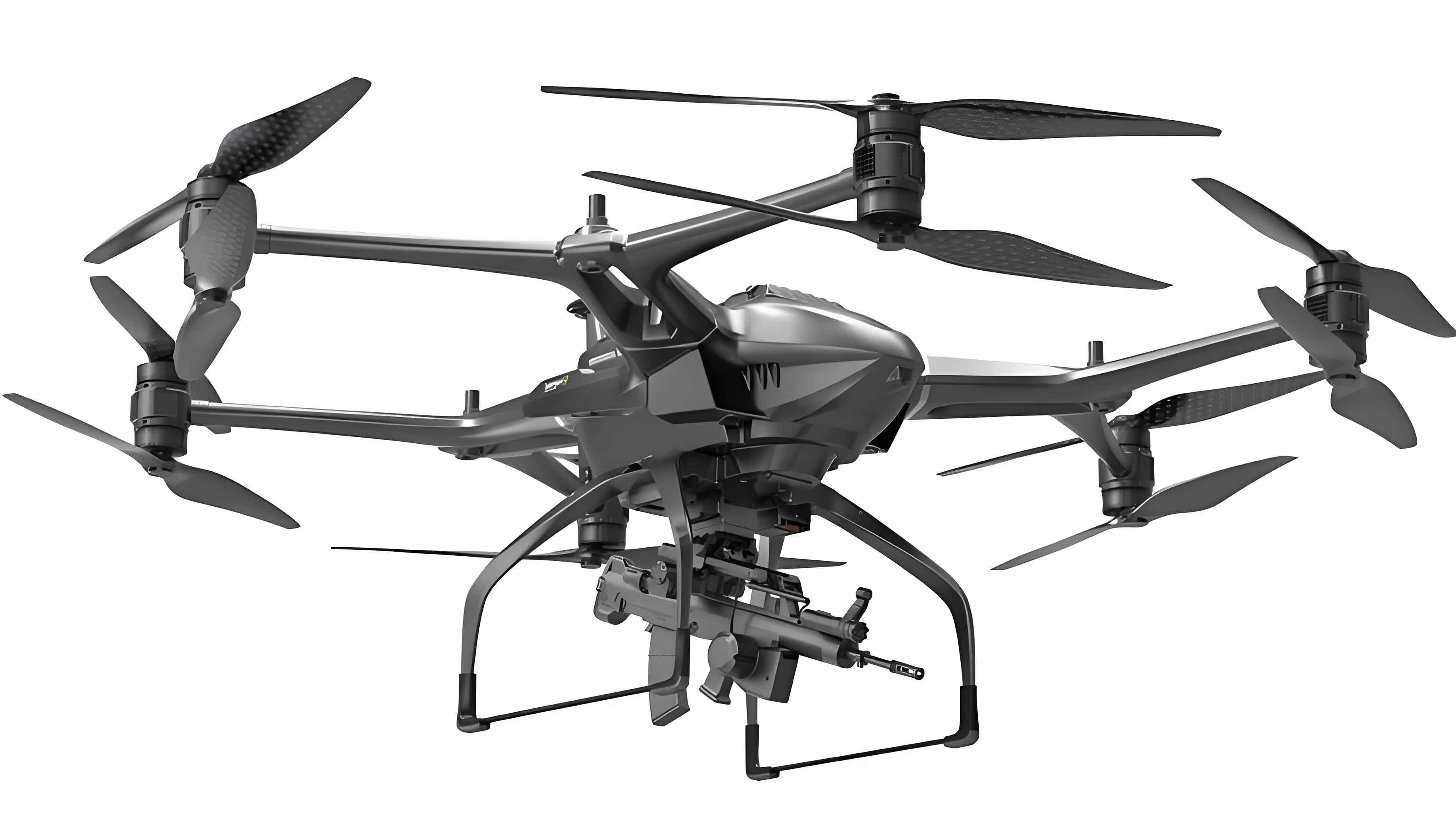
Military maintenance doctrine typically follows a three-echelon structure: Organizational/Field Level (fault isolation to the Line-Replaceable Unit – LRU), Intermediate Level (fault isolation to the shop-replaceable module/card), and Depot/Base Level (fault isolation to the failed component). Our field checker is designed explicitly for the Organizational Level. Its primary mission is to quickly verify the functionality of a military drone’s transponder or isolate a fault to an LRU (e.g., the entire transponder unit, or its major sub-assemblies like the RF module or processor card), enabling swift restoration of operational capability. The design priorities are comprehensive test coverage, minimal size and weight, and operational simplicity for use in challenging field conditions.
Overall System Design and Technical Characteristics
Equipment Architecture
The field checker employs a fully integrated, handheld design. It consolidates the power supply, RF transceiver assembly, digital signal processing board, display, keypad, and necessary avionic or RF connectors into a single, ruggedized enclosure. The block diagram below illustrates the core components and their interconnections:
System Block Diagram: External Power Input -> Power Module -> +5V & +3.3V Distribution. The keypad provides user input to the Signal Processing Board (featuring a DSP and FPGA). The Processing Board controls the Transceiver Module (containing synthesizers, modulators, power amplifiers, low-noise amplifiers, and mixers). The Transceiver interfaces with the Antenna Port. Received signals from the Transceiver are sent to the Processing Board for analysis, and results are displayed on the OLED Screen. A CAN Bus interface connects to the Unit Under Test (UUT) for data loading and configuration.
The operational workflow is straightforward. The power module converts an external DC supply (e.g., from a vehicle or battery) into the stabilized low-voltage rails required internally. User commands are entered via the membrane keypad, initiating test sequences. The heart of the system is the signal processing board, which generates interrogation codes, controls the RF transceiver, decodes reply signals, and manages the user interface.
Key Technical Features
The design philosophy centers on high-density modularization to achieve portability without sacrificing capability. Key features include:
- Ultra-Compact Interconnects: Internally, submodules (transceiver, power, processing) are interconnected using super-miniature rectangular connectors from suppliers like Guihang Group. This reduces board footprint, improves reliability over solder-only connections, and facilitates module replacement if needed.
- Wide-Temperature OLED Display: A dot-matrix Organic Light-Emitting Diode (OLED) display is used for its excellent viewing characteristics, low power consumption, and robust operational temperature range (-40°C to +55°C), which is crucial for military drone support in varied climates.
- Intuitive Menu System: The software features a hierarchical menu interface with clear prompts and result presentation, enabling technicians to perform complex checks efficiently with minimal training.
- Quick-Detach Antenna: A standard RF connector (e.g., TNC) allows for rapid attachment of different antennas suited for the test range or environment, enhancing adaptability.
- Ruggedized Enclosure: The main housing is machined from a single block of aluminum alloy, providing superior structural integrity, electromagnetic shielding, and heat dissipation. Fins are machined into the case near the power components to aid passive cooling.
The core specifications of the field checker are summarized in the table below:
| Parameter | Specification |
|---|---|
| Dimensions | Approx. 180mm x 100mm x 40mm |
| Weight | < 1.2 kg |
| Operating Temperature | -40°C to +55°C |
| Power Supply | 18-32 VDC |
| Power Consumption | < 15 W |
| RF Frequency (Interrogation) | 1030 MHz ±1 MHz |
| RF Frequency (Reply) | 1090 MHz ±1 MHz |
| Supported Modes | ATC Mode A, Mode C, Military Modes |
| Interface | RF Port (Antenna), CAN Bus, Power |
Operational Theory and Workflow
The checker operates on the secondary surveillance radar principle, using an interrogate-respond protocol to test the military drone’s transponder. It emits coded RF interrogation pulses. The UUT (the drone’s transponder) receives these, decodes them, and, if functioning correctly, replies with its own coded RF pulse group. The checker analyzes the presence, timing, and code structure of this reply to determine pass/fail status.
Pre-Test Preparation: Software and Configuration Loading
A critical security feature of military drone electronics is the use of volatile memory for operational software. This allows for data destruction in emergency scenarios to prevent compromise. Consequently, before a flight, the ground support equipment must first load the operational software and necessary data (e.g., encryption keys) into the military drone’s avionics.
This process also serves as an initial functional check. The field checker connects to the transponder via the CAN bus. The operator uses the keypad to select the appropriate software image and crypto keys stored internally on the checker. The data is transmitted to the UUT. Successful loading verifies the integrity of the CAN interface and the UUT’s basic processing capability. Following this, configuration commands (e.g., setting operating modes, power levels) are sent via the same bus to prepare the transponder for testing and flight.
Functional Testing Sequence
After the checker confirms its own power and self-test status, it proceeds to test the military drone’s transponder. The primary test modes are:
- ATC Function Check: The operator selects ATC interrogation. The checker transmits Mode A (identity) and Mode C (altitude) interrogation pulses. A functional transponder will reply with the appropriate pulse groups. The checker calculates the reply probability, $P_{reply}$, over a series of interrogations:
$$ P_{reply} = \frac{N_{valid}}{N_{interrogated}} $$
where $N_{valid}$ is the number of valid replies detected and $N_{interrogated}$ is the number of interrogations sent. A $P_{reply}$ above a defined threshold (e.g., 90%) indicates normal ATC function. Failure here can be isolated by swapping LRUs on the military drone’s transponder if it is modular. - Military Code (Identification) Check: The operator selects military identification mode. The checker transmits encrypted or coded interrogation pulses specific to military IFF systems. The transponder’s secure reply is analyzed. The checker can cycle through different assigned codes to verify each one. Similar probability analysis is performed. Failure in this mode, but success in ATC mode, can help isolate faults to specific cryptographic or signal processing chains within the UUT.
The test functions and their corresponding checker actions are summarized below:
| Test Function | Checker Action | Expected UUT Response | Fault Isolation Indication |
|---|---|---|---|
| ATC Mode A | Transmit P1, P3 pulses spaced 8µs. | Reply with 12-pulse identity code. | Low reply probability indicates ATC receiver/processor fault. |
| ATC Mode C | Transmit P1, P3 pulses spaced 21µs. | Reply with 12-pulse altitude code. | Failure in altitude digitization or encoding. |
| Military Mode | Transmit encrypted challenge pattern. | Reply with encrypted response pattern. | Failure indicates crypto module or secure processing fault. |
| CAN Bus Loading | Transmit software & key data packets. | Accept packets & return ACK. | No ACK indicates CAN interface or core processor fault. |
Detailed Circuit Design
Signal Processing Board
This board is the computational center. Our design integrates control, encoding, decoding, local code generation, digital down-conversion, A/D sampling, and interface management onto a single board using a System-on-Chip (SoC) approach centered on a DSP and FPGA.
The received signals from the transceiver assembly are of two types: an analog ATC video signal (pulse envelopes) and a digitized IF signal for military waveforms. The ATC video is conditioned and directly sampled. The IF signal, centered at an intermediate frequency (e.g., 60 MHz), is first sampled by a high-speed ADC. We selected the LTC2299, a dual 14-bit 80 MSPS ADC from Linear Technology, for its excellent dynamic performance and low power consumption, a critical consideration for our portable military drone support tool.
The sampled data streams are fed into the FPGA. Here, the IF signal undergoes digital down-conversion (DDC) to baseband using a Numerically Controlled Oscillator (NCO) and digital mixers, followed by filtering and decimation. The baseband military signal and the sampled ATC pulses are then processed (despreading, decoding, pulse timing measurement) within the FPGA. The results are passed to the DSP (e.g., a Texas Instruments TMS320C6000 series) for higher-level analysis, probability calculation, and management of the user interface and system control.
Power integrity is paramount, especially for the ADC. We isolate its power rail using a dedicated dual-output regulator, the TPS70302 from TI, which provides a clean, low-noise supply. The rest of the board is powered by a compact DC-DC converter module. All components are surface-mount to minimize board area.
The signal flow can be modeled. For the military waveform processing, the received IF signal after sampling is:
$$ s_{IF}[n] = A[n] \cdot cos(2 \pi (f_{IF}/f_s) n + \phi[n]) + w[n] $$
where $A[n]$ and $\phi[n]$ carry the modulation, $f_s$ is the sampling rate, and $w[n]$ is noise. The DDC in the FPGA performs:
$$ I[n] = s_{IF}[n] \cdot 2 \cdot cos(2 \pi f_{LO} n / f_s) $$
$$ Q[n] = -s_{IF}[n] \cdot 2 \cdot sin(2 \pi f_{LO} n / f_s) $$
where $f_{LO}$ is the digital LO frequency set to $f_{IF}$. After low-pass filtering, we obtain the complex baseband signal $I[n] + jQ[n]$ for further demodulation and decoding.
RF Transceiver Assembly
This module handles all RF functions. Its design focuses on stability, spectral purity, and sufficient output power for short-range testing of the military drone transponder.
Transmit Path: A low-phase-noise frequency synthesizer (e.g., based on the SWM501K chip) generates both the RF carrier (1030 MHz) and the Local Oscillator (LO) signal. The RF carrier is pulse-modulated by a high-speed switch according to the interrogation code from the processing board. This pulsed RF is amplified by a driver and a final power amplifier (PA) to achieve the required output level (typically a few watts). A transmit/receive (T/R) switch or circulator routes this signal to the antenna port.
Receive Path: The weak reply signal from the military drone’s transponder (at 1090 MHz) is received via the antenna. It passes through the T/R switch to a Low-Noise Amplifier (LNA) to improve the signal-to-noise ratio. This amplified signal is then mixed with the LO signal (which is first divided and amplified) to down-convert it to an Intermediate Frequency (IF). For military waveforms, this IF (e.g., 60 MHz) is bandpass filtered and sent to the processing board for digitization. For the ATC video, the 1090 MHz signal is passed through an envelope detector (diode) to extract the pulse video, which is then filtered and sent to the processing board.
The key RF performance parameters are critical for reliable testing of the military drone’s equipment:
| Parameter | Transmit Path | Receive Path |
|---|---|---|
| Frequency Accuracy | ±0.5 ppm | N/A |
| Output Power | +43 dBm (min) | N/A |
| Pulse Rise/Fall Time | < 0.1 µs | N/A |
| Receiver Sensitivity | N/A | -77 dBm (for Preply>0.9) |
| Dynamic Range | N/A | > 70 dB |
| Noise Figure | N/A | < 4 dB |
The link budget for the test can be approximated. The power at the receiver of the military drone transponder, $P_{rx,UUT}$, is given by:
$$ P_{rx,UUT} = P_{tx,checker} + G_{tx} – L_{path} + G_{rx,UUT} $$
where $P_{tx,checker}$ is the checker’s transmit power, $G_{tx}$ and $G_{rx,UUT}$ are antenna gains, and $L_{path}$ is the free-space path loss. For a short test range $r$ (e.g., 10 meters) at 1030 MHz, the path loss is:
$$ L_{path} (dB) = 20 \log_{10}(r) + 20 \log_{10}(f) – 147.55 \approx 51.7 \text{ dB} $$
This ensures a strong signal at the UUT even with low-gain test antennas.
Mechanical and Software Architecture
Structural Design
The mechanical design is driven by requirements for shock/vibration resistance, environmental sealing (to meet IP54 or similar), and thermal management. As mentioned, the main body is a single aluminum alloy casting with machined fins for heat dissipation. The rear cover is a flat aluminum plate secured with countersunk screws, providing a flush surface and good sealing. Internal boards are mounted on standoffs and connected via the aforementioned miniature connectors. The overall structure is designed to withstand the vibrations associated with transport in a military vehicle supporting drone operations.
Firmware Design
The software is partitioned between the FPGA and the DSP for optimal performance.
FPGA Firmware: The FPGA (e.g., a Xilinx Spartan-6 or Artix-7) handles all time-critical, high-throughput tasks. Its program is structured into several concurrent modules:
- Interrogation Code Generator: Creates precise P1, P3, and control pulse patterns for ATC and military modes.
- Transceiver Controller: Manages the RF module’s timing, gain control, and mode switching.
- Digital Down-Converter (DDC): Implements the NCO, mixers, and FIR filters for the military IF signal path.
- Pulse Detection & Timing: Measures the arrival time and width of received ATC video pulses with high precision (e.g., 10 ns resolution).
- Interface Manager: Handles low-level communication with the ADC, DAC, and the DSP via a parallel or high-speed serial bus (e.g., EMIF, SPI).
DSP Software: The DSP runs the main control algorithm and user interface. Its tasks include:
- Interpreting user keypad input and managing the OLED display menu system.
- Calculating reply probabilities ($P_{reply}$) and comparing them to thresholds.
- Managing the file system for stored software images and crypto keys.
- Implementing the CAN bus protocol stack for communication with the military drone transponder.
- Coordinating test sequences by sending commands to the FPGA control registers.
Conclusion
The portable field checker described herein provides an effective solution for the Organizational-Level maintenance of military drone-borne transponders. By adopting a highly integrated modular design, employing wide-temperature components, and implementing an intuitive software interface, the device meets the critical demands for portability, rapid deployment, and reliable operation in harsh field environments. It enables technicians to quickly verify the functionality of a military drone’s critical identification equipment or isolate faults to an LRU, significantly enhancing the operational availability and turnaround time of military drone assets. Future developments may include the integration of additional wireless test interfaces, more advanced diagnostic algorithms using machine learning for fault prediction, and even smaller form factors leveraging newer system-in-package (SiP) technologies. The core principle remains: providing robust, frontline technical support for the increasingly sophisticated electronic systems carried by modern military drones.